46
Systems, Controls and Operations
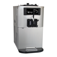
Models C708/C709/C716/C717
Checking and Setting Refrigeration Valves
This machine is equipped with a safety door lock.
Freezer operation is not allowed in the AUTO,
STANDBY or WASH modes if the door is off. In
order to perform a frost check or a beater rotation
check, the technician must use a magnet to bypass
the reed switch located behind the front panel.
Note: To check various pressures in the
refrigeration system, the machine must be
assembled and have product in both the hopper and
the freezing cylinder.
Gauges should not be installed on these freezers
unless a problem is suspected with the refrigeration
system. Once you have determined there is a
problem, perform the following procedures:
Step 1
Install refrigeration gauges on the service valves
located behind the lower front panel. Remove the
safety cover f or complete access.
Step 2
Install a suction line gauge on the schrader valve
fitting on the EPR valve. (See the refrigeration
schematic.)
Step 3
Set the DBV valve (discharge bypass valve) by
placing the freezer in STANDBY. When the freezing
cylinder is satisfied and the hopper only is still
cooling adjust the DBV valve to 10 - 11 psi (69 - 76
kPa) by reading the suction gauge at the service
valves. Adjust the EPR valve to 60 psi (414 kPa) by
reading the suction gauge on the EPR access fitting.
Step 4
When the freezer has cycled off, place the unit in
AUTO. Set the freezing cylinder expansion valve to
20 to 22 psi (138 to 145 kPa) and the water valve to
255 psi (1,758 kPa) if so equipped.
Step 5
Place the freezer into a heat cycle. The hopper only
will heat for the first 10 minutes and then the
freezing cylinder will begin to heat.
Step 6
Once both the hopper and the freezing cylinder are
above 100°F (38°C), set the OPR valve to 40 psi
(276 kPa) by reading the pressures at the service
valves.
Failure to follow these procedures will result in
improperly set valves and poor freezer performance.
To reclaim and recharge a system, install a jumper
on W4 on the interface board to open all solenoids.
Remove the jumper upon completion of the recharge
and check valve settings as outlined above.
Note: Each side must be set individually on the
C716 and C717.