CHAPTER 6 – LUBRICATION / FILTERS / FLUIDS
6-30
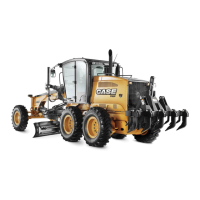
Hydraulic System Oil Filter
Check each 500 hours
WARNING: Fluid under pressure. Turn cap
slowly to relieve pressure before removing it.
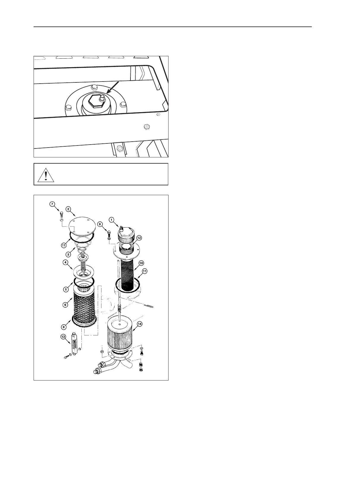
Loosen ller cap (1) to relieve pressure. Remove cover
(2) from top of the tank. Remove spring (3), cap (4) and o-
ring (5 and 11), from top of element (6). Remove element
from tank and discard.
Remove the element of the reservoir. Make sure the o-
ring (8) is in good condition, if necessary, replace it and
then install a new lter over the discharge tube. Make
sure the o-ring (5 e 11) is in good condition, if necessary,
replace it. Position o-ring (5 e 11). install the cap (4) and
spring (3) on top of the element.
Install cover (2) on tank and secure with capscrews (7).
Torque capscrews to 47,5 to 54,2 Nm (4,9 to 5,5 kgf.m)
(35 to 40 lb.ft).
CLEANING THE SUCTION LINE FILTER
Loose the ller neck cap (1) to relieve the pressure. Re-
move the ller neck capscrews (9), the tube and the lter.
Remove the ller neck cover, the tube (10) and lter (14)
from the hydraulic. Remove and replace the rubber ring
(11) from lter, if necessary.
IMPORTANT: Do not use gasoline, solvent or another
ammable uids to wash the components. Use recom-
mended commercial, non toxic solvent. Wear safety glas-
ses with side shields when using compressed air for cle-
aning to reduce the danger of personal injury from ying
particles. Limit the air pressure to 30 PSI (2 bar).
Wash the strainer with a commercial solvent. Use com-
pressed air to clean the element (14). Blow it from inside
to outside.
Install a new o-ring in the groove and then install the tube
assembly (pre cleaner) (10).
Install the capscrews (9) and torque them with 47,5 to
54,2 Nm (4,9 to 5,5 kgf.m) (35 to 40 lb.ft).
Make sure that valve assembly and strainer are properly
positioned in the tube assembly. Fill the tank to the proper
level indicated on the sight gauge (13). Install a new o-ring
(12) on the ller cap and install it.