CHAPTER 8 – ELECTRICAL SYSTEM
8-7
845B / 865B / 885B with FUNK Transmission
Before performing any welding work on the machine, turn
off the ignition switch, making sure to place it to the “OFF”
position. Connect the ground cable of the welding equip-
ment to a maximum distance of 0,6 m (2 ft) from the part
being welded.
For a safe welding procedure performance, some electro-
nic component connectors must be disconnected. Make
sure to disconnect the connectors listed below:
X23
X24
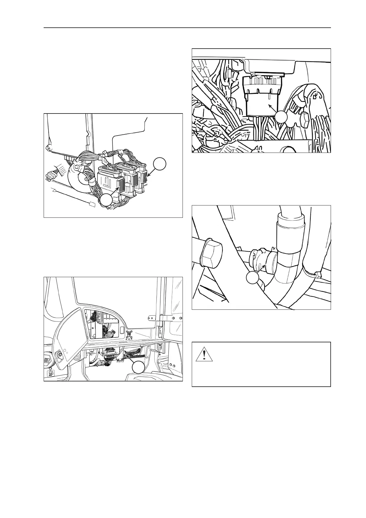
X23 – TCU GRAY CONNECTOR
X24 – TCU BLACK CONNECTOR
Transmission control module (TCU) – On the right
side of the operator cabin, 3 transmission control module
connectors are located. Make sure to disconnect the X24
black connector and the X23 gray connector.
X6
X6 – LATERAL PANEL CONNECTOR
Front panel – Disconnect the 70-pin X6 connector from
the front panel, located on the right hand-side of the rear
chassis, between the cabin mounting brackets. To discon-
nect, loosen the center screw on the connector using a 4
mm Allen wrench.
J4
J4 – FUNK TRANSMISSION SELECTOR LEVER CONNECTOR
Transmission selector lever – Disconnect the J4 con-
nector from the selector lever, located on the right side
console, above the fuse boxes and below the transmis-
sion gearshift selector lever itself.
J6
Transmission – Disconnect the J6 connector , located
on the left hand-side of the machine, next to the trans-
mission.
CAUTION: If a welding work is performed wi-
thout disconnecting the above described con-
nectors, irreparable damages may occur to the
control module, to the transmission and to the
front panel of the machine.