Assembly and operating instructions
CENTAX-G
020G-00050…00090-F.10
CENTA Antriebe Kirschey GmbH 5 / 52
Index of illustrations
Fig. 5-1 Axial misalignment ........................................................................ 15
Fig. 5-2 Radial misalignment ...................................................................... 16
Fig. 5-3 Angular misalignment .................................................................... 18
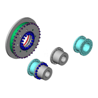
Fig. 6-1 Example: 020G-00050...00090-F.10 ............................................... 22
Fig. 6-2 Mounting the hub with cylindrical bore and keyway ........................... 24
Fig. 6-3 Mounting the hub with conical oil interference fit .............................. 26
Fig. 6-4 Mounting the adapter (17; if existing) ............................................. 29
Fig. 6-5 Positioning the membrane (1.2.1) ................................................... 30
Fig. 6-6 Positioning the ring (1.4) inside the rubber element (1.1) .................. 31
Fig. 6-7 Mounting the pre-mounted rubber element (F) to the flywheel ........... 32
Fig. 6-8 Positioning the rubber element (1.1) and the ring (1.4) ..................... 33
Fig. 6-9 Mounting the adapter (4) to the flywheel ......................................... 34
Fig. 6-10 Mounting the rubber element (1.1) and the ring (20; if existing)
to the adapter (4) ....................................................................... 35
Fig. 6-11 Mounting the ring (1.4) ................................................................ 37
Fig. 6-12 Mounting the membrane (coupling sizes 00050…00075) .................. 38
Fig. 6-13 Mounting the membrane (coupling sizes 00078…00090) .................. 39
Fig. 6-14 Connecting the rubber element (1.1) and the membrane ................. 40
Fig. 6-15 Detail X ..................................................................................... 40
Index of tables
Table 2-1 Shape and size of ventilation holes ................................................ 9
Table 5-1 Permissible radial alignment tolerance .......................................... 17
Table 5-2 Permissible angular alignment tolerance ........................................ 19
Table 7-1 Troubleshooting table ................................................................. 42