CENTRALINE I/O MODULES – INSTALLATION & COMMISSIONING INSTRUCTIONS
EN1Z-0973GE51 R0119
28
Technical Data
Table 33. Analog output module data
Voltage rating 0(2)…11 V (default)
Current rating max. ±1 mA
Resolution 8 bit
Accuracy ±150 mV
Zero output voltage < 200 mV
Protection
Protected against 24 VAC and
40 VDC overvoltage as well as
against short-circuiting
Feedback signal
Auto/manual mode and output
value
Status LED Behavior
Table 34. Analog output status LED behavior
Automatic mode
Brightness follows the
commanded output signal
Override mode Flashes
Status LEDs with Manual Overrides
12
3
4
5
678
UTO
0
!
100
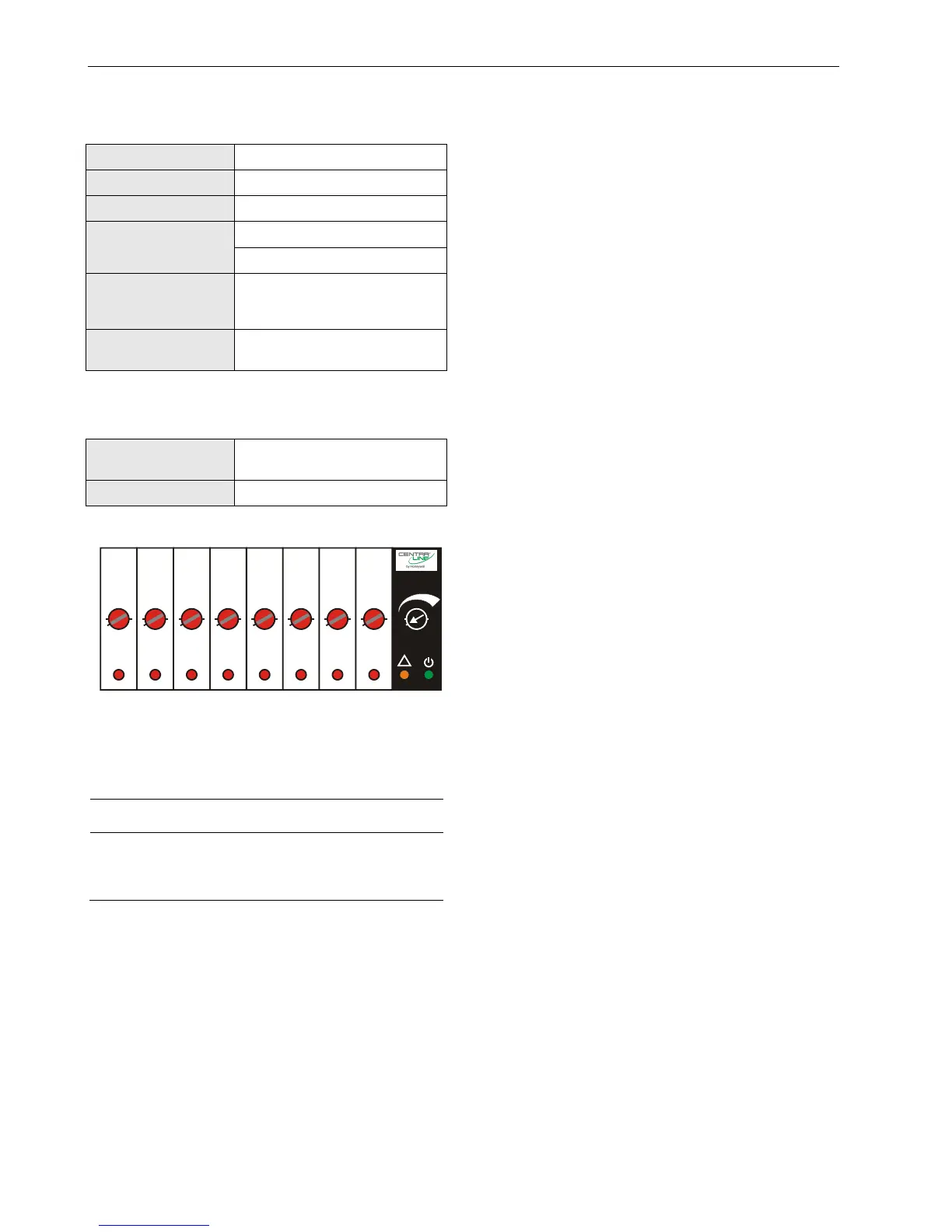
Fig. 37. Manual overrides (rotary knobs)
The CLIOPR822A/CLIOLR822A Analog Output Modules are
equipped with manual overrides: one for each analog output.
These rotary knobs can be manually set to either "AUTO" or
"0…100%" (infinitely adjustable).
NOTICE
Damage to the electronic module!
► Do not use a tool to adjust the rotary knobs.
► Do not use excessive force. Adjust only by hand.
Manual Override in the AUTO Position
When a manual override of the CLIOPR822A/CLIOLR822A is
set to AUTO, and the corresponding analog output has been
configured, the following applies:
If the L
ONWORKS network is functioning properly, the
output voltage of the analog output will be as
commanded.
If the L
ONWORKS network is not functioning properly, the
output voltage of the analog output will be the safety
position value.
The brightness of the status LED (red) of the analog
output will be proportional to the commanded output
signal.
When a manual override of the CLIOPR822A/CLIOLR822A is
set to AUTO, and the corresponding analog output has not
been configured, the following applies:
Regardless as to whether the L
ONWORKS network is
functioning properly or not, the output voltage of the
analog output will be 0 V (values from the L
ONWORKS Bus
will be ignored, and there will be no heartbeat or safety
position).
The feedback signal on the L
ONWORKS network
nvoAoActPosnFb[ ] will have a value of 0% and a state of
0.
The analog output status LED will be dark.
Manual Override in the Override Position (0…100%)
When a manual override of the CLIOPR822A/CLIOLR822A is
set to 0…100%, and the corresponding analog output has
been configured, the following applies:
The output voltage of the analog output will be 0…10 V
(direct) or 10…0 V (reverse).
The feedback signal on the L
ONWORKS network
nvoAoActPosnFb[ ] will have a value of 0…100% and a
state of -1.
The status LED (red) of the analog output will flash to
indicate “manual override.”
When a manual override of the CLIOPR822A/CLIOLR822A is
set to 0…100%, and the corresponding analog output has
not been configured, the following applies:
The output voltage of the analog output will be 0…10 V.
The feedback signal on the L
ONWORKS network
nvoAoActPosnFb[ ] will have a value of 0…100% and a
state of -1.
The status LED (red) of the analog output will flash to
indicate “manual override.”
Analog Outputs Configured as Binary Outputs
Using the engineering tool, the analog outputs can be con-
figured individually as binary outputs. The voltage output is
then 0 V or 10 V, depending upon the signal from the con-
troller.
 Loading...