page 23 www.centsys.com
OPERATOR INSTALLATIONSECTION 6
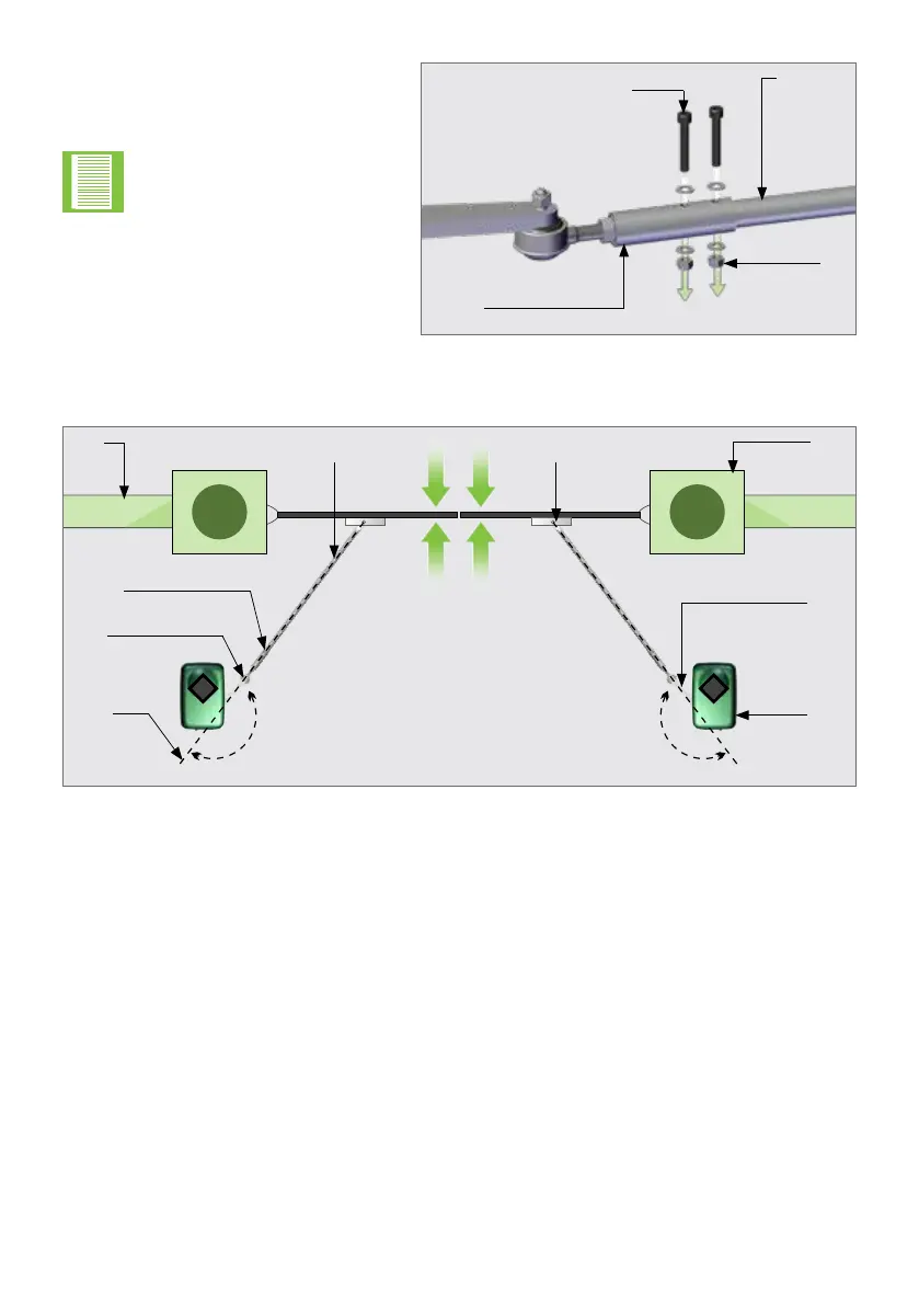
FIGURE 17
Adaptor
piece
Nut
M8 x 40
Set screw
Connecting
Arm
Step 12
Align the gate end-points.
FIGURE 18
Setup
line
Ball
joint
Connecting Arm
adapter
Pillar
Motor
Wall
Connecting
Arm
Align gate
end-points
180° 180°
Gate
Bracket
Drive
Arm
Step 11
Fit the Bolts and Nuts through the
xingholesintheConnectingArm
Adaptor and the Connecting Arm.
Step 10
Drill2xØ8mmxingholesinthe
Connecting Arm.
Holes bigger than Ø8mm
will result in unwanted play
in the Connecting Arm.