page 27 www.centsys.com
Step 14
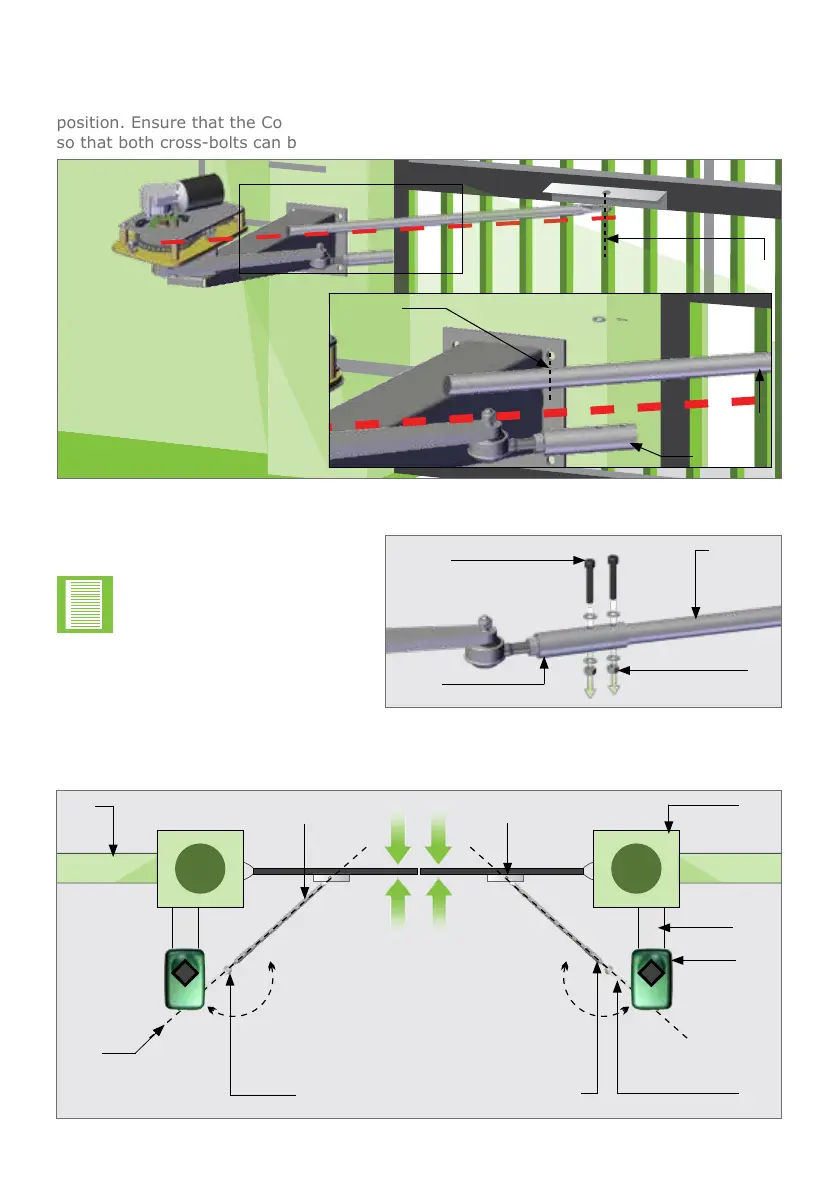
Align the gate end-points.
OPERATOR INSTALLATIONSECTION 6
Step 13
Fit the Bolts and Nuts through the
xingholesintheConnectingArm
Adaptor and the Connecting Arm.
FIGURE 28
Adaptor
piece
Nut
M8 x 40
Set screw
Connecting
Arm
FIGURE 29
Setup
line
Ball
joint
Connecting Arm
adaptor
Pillar
Motor
Wall
Connecting
Arm
Align gate
end-points
Gate
Bracket
Drive
Arm
Wall
mount
Step 11
LooselyttheDriveArmtotheConnectingArmsothatitcanbecuttothecorrectlength
once the Drive Arm and Connecting Arm are collinear and with the gate in the closed
position.EnsurethattheConnectingArmhassucientlengthwithintheconnectingtube
so that both cross-bolts can be used.
FIGURE 27
Cut here
Connecting
Arm
Drive Arm
Attach Connecting Arm to the
Gate Bracket and gate
Ball
joint
180° 180°
Step 12
Drill2xØ8mmxingholesinthe
Connecting Arm.
Holes bigger than Ø8mm
will result in unwanted play
in the Connecting Arm.