1.6.1.1 SINGLE SOURCE CONNECTIONS (STANDARD)
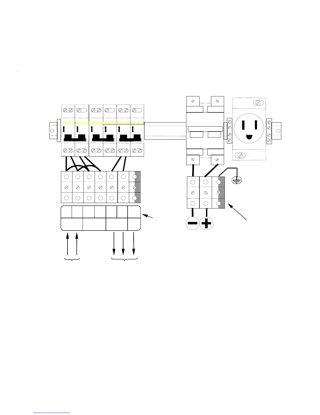
The UPS comes shipped configured for a single AC input as shown in
Figure E below.
I O
0
OF
I O
0
OF
0
OF
I O
I O
0
OF
0
OF
I O
I O
0
OF
QS1 QS3 QS4
QS5
LIFE MODEM
POWER
SUPPLY
Label,
Terminal
Blocks
UPS
OUTPUT
LINE
INPUT
GND B A L2 L1
Equipment Ground to
Battery Cabinets
Extended Run
Battery
Connection
(if present)
To Output
Cabinet
Utility
Input
Figure E: Single AC Source
The configuration shown in Figure E details the connections when the UPS is fed by a
single AC source. In this configuration the rectifier, bypass and maintenance bypass lines
are all fed by the same source.
Connect your utility input wires to the Utility Input terminals (marked L1 and L2) on the far
left of the terminal rail. Note that the second set of terminal blocks is not used in this
configuration.
15



 To Next Page