1.6.1.2 CONFIGURING THE UPS FOR A DUAL FEED INPUT
I O
0
OF
I O
0
OF
0
OF
I O
I O
0
OF
0
OF
I O
I O
0
OF
QS1 QS3 QS4
QS5
L1 L2 A B GND
LINE
INPUT
UPS
OUTPUT
Jumpers to Remove
for Dual Input
LIFE MODEM
POWER
SUPPLY
Label,
Terminal
Blocks
Equipment Ground to
Battery Cabinets
Extended Run
Battery
Connection
(if present)
To Output
Cabinet
Utility
Input
Bypass
Input
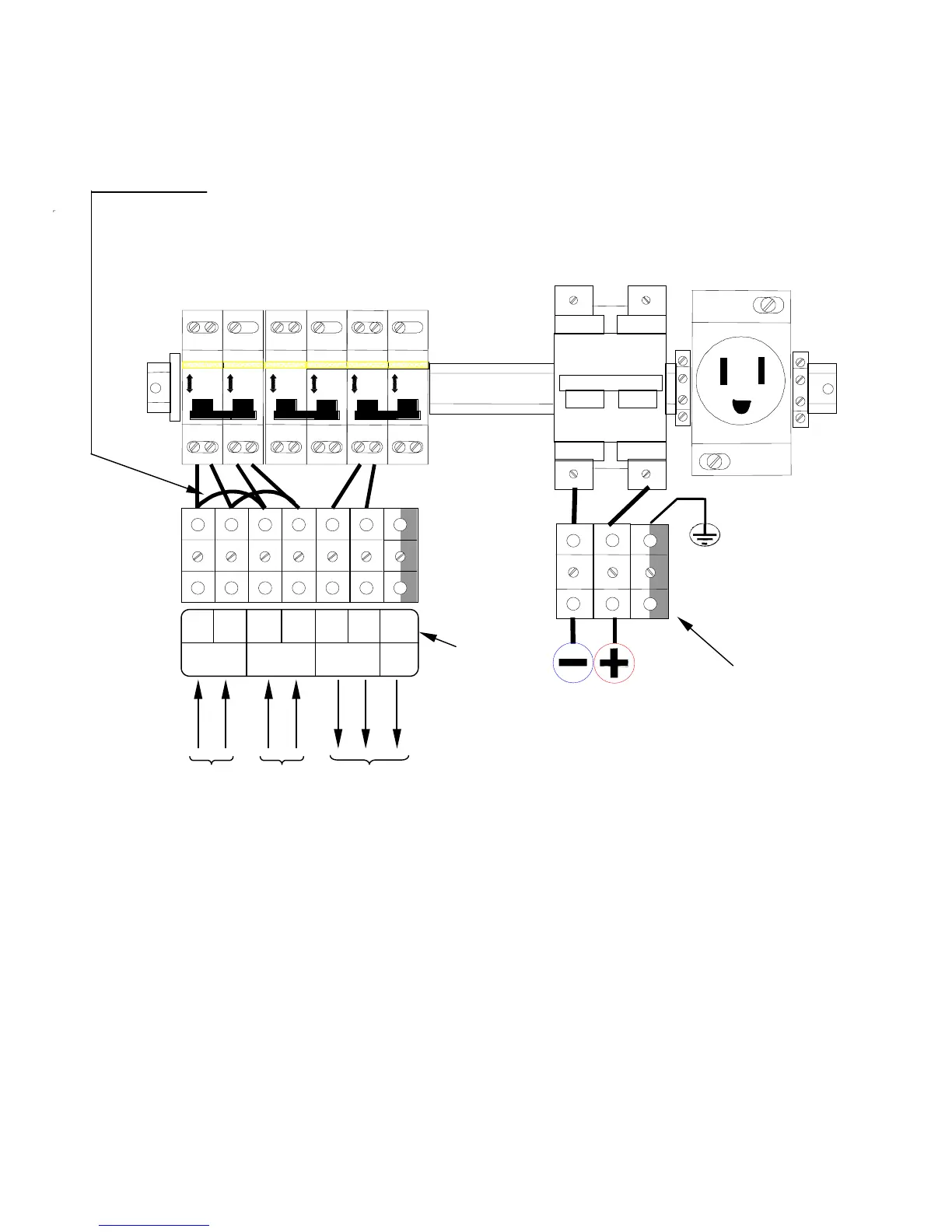
Figure F: Dual AC sources
Removing the jumpers shown in Figure F allows the UPS bypass line to be fed by a
separate source. Two (2) jumpers to remove are between L1 and third terminal from the
left and L2 and fourth terminal from the left. The configuration shown in Figure F shows
the terminal connections necessary when a second source is brought to the UPS. “Bypass
line” supplies the static bypass line and the maintenance bypass line, while “Utility input”
supplies the rectifier and inverter of the UPS.
After removing the jumpers shown in Figure F, connect your bypass source wires to the
“Bypass Line” terminals L1 and L2. Connect your main utility input wires to the two
terminal blocks immediately to the right of the “Bypass Line” terminals (there is no
designation on the terminal block label for these terminals, consult the factory for
clarification and instruction if necessary.)
16
 Loading...