4.0 AUXILIARY AND OPTIONAL EQUIPMENT
This section provides descriptions of the auxiliary and optional equipment available on the
Synthesis™ Uninterruptible Power Supply system. Some options are factory installed and
the user installs others. Interconnection wiring instructions are provided where necessary.
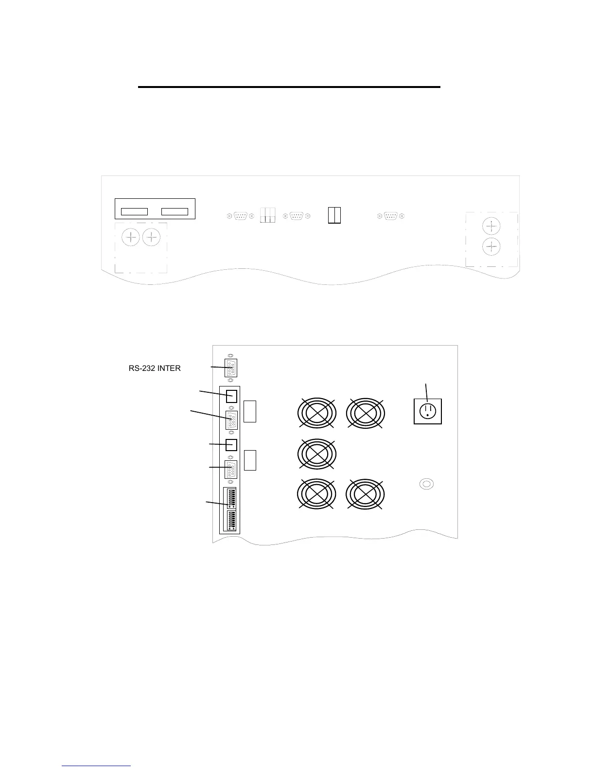
UPS module connections are made at the rear of the cabinet. See Figure Z or AA for
connector locations.
Remote
EPO
4-6 kVA
F7
F8
SW2 SW1
F7
F8
8-12 kVA
Port
RS232
ALAR
SUMMAR
RS232
(Used by front
panel display)
COMPUTE
INTERFA
CE
Figure Z: UPS Module Interface Connector Locations 4-12kVA. (Back of Unit)
RS-232 INTERFACE
REMOTE EPO
TERMINAL
RS-232
(USED BY FRONT
PANEL DISPLAY)
SUMMARY ALARM
AS/400
TM
INTERFACE
DIP SWITCHES
MODEM
POWER
SUPPLY
Figure AA: UPS Module Interface Connector Locations 14-18kVA. (Back of Unit)
4.1 INTERFACE
4.1.1 DISPLAY
The back-lit liquid crystal alphanumeric display has a total of 24 characters arranged in
two lines; it provides a means of communication with Synthesis™ through display of
operating parameters and measured values.
39
 Loading...