Section 1: Introduction
Christie ACT User Manual 1-5
020-100129-05 Rev. 1 (02-2010)
1.3.1 Key Features
• Inputs - 16 opto-isolated inputs
• Outputs - 14 relays Single Pole Single Throw (SPST)
• GPIO - 7 non-isolated with 12V rail
• Control Interface - 8 front panel buttons
• Power - Dual voltage (120/240 VAC) input
• Accessory Power - 12V and 5V terminals
• Dimensions - 2 Rack Unit Height
• Web User Interface
• Serial Control RS232 and RS422
•Ethernet
• RS232 (loop-through)
• 14 programmable LEDs
• Status LEDs
• Available Buzzer (user configured)
1.3.2 Inputs
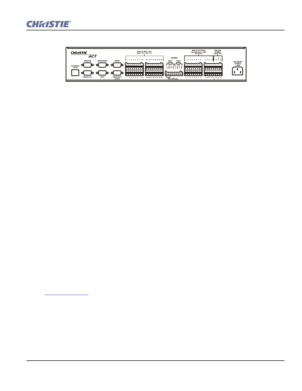
There are 16 inputs (32 terminals) located on the back panel of Christie ACT. (Figure 1-2). There is an option
to internally pull up any of the inputs to an isolated 5V via software control. The input pull-up feature is
disconnected by default.
The internal pull-up to 5V is useful when interfacing with other equipment's contact closures (such as relays).
The internal input pull-ups provide a voltage to active the inputs.
If available, an emergency situation input can be connected and the automation is able to control the
appropriate auditorium functions (lights up, projector off, etc.) in case of an emergency. Refer to
Section 3 Operation
.
1.3.3 Outputs
There are 14 relay outputs (28 terminals) all of which are normally open (N/O) single pole single throw (SPST)
located on the back panel of Christie ACT. The first 12 are rated for 1A, and the last two are rated for 8A. The
external power terminals can be connected to allow the relay outputs to carry some voltage.
Relays can be grouped together (connect common for multiple signals) by using jumper leads at the
connectors.
Figure 1-2 Chrisite ACT Back Panel