2-2 Christie ACT User Manual
020-100129-05 Rev. 1 (02-2010)
Section 2: Installation & Setup
2.1 General Information
The Christie ACT unit is designed for installation in a CP2000 projector pedestal or, more typically, in a
Mounting Rack like the CP2000ZX or M rack stand.
NOTE: The Christie ACT unit is intended for installation in a RESTRICTED ACCESS LOCATION only.
1) Installation to be performed by a Qualified Service Technician only. 2)
Disconnect all power before servicing!
Before you begin installation, it is important to fully understand all site requirements and characteristics.
Christie ACT DOES NOT have an internal battery. If AC Power is interrupted
Christie ACT will abort the ongoing program and will reset to an OnDeviceStartup condition
which means the system will re-initialize.
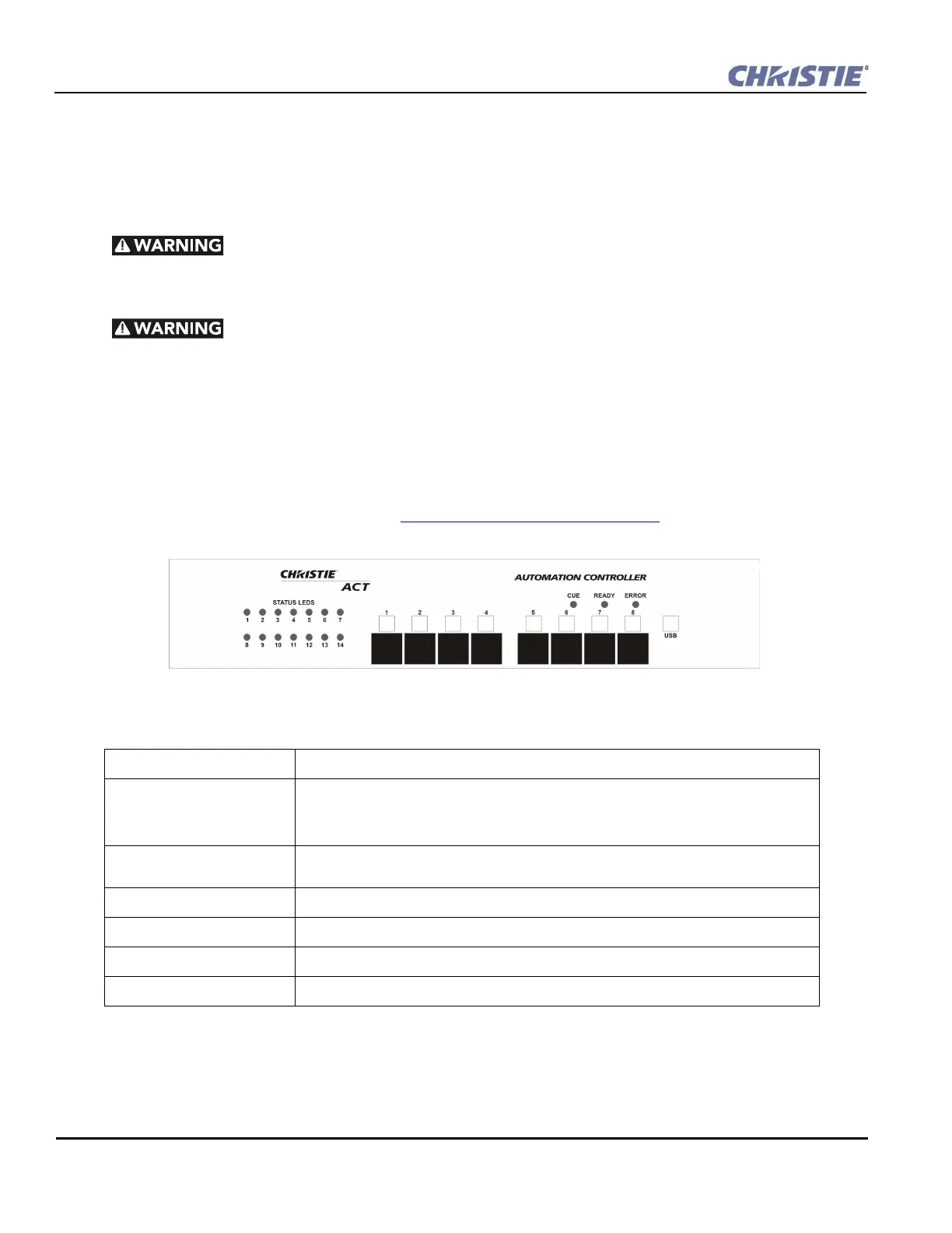
2.2 Front Panel
2.2.1 Mounting Points
Mounting points enable Christie ACT to be installed in the rear of the CP2000 pedestal, or be rack-mounted in
a separate standard 19-inch rack. Refer to Section 2.5.1 Rack Mount Installation
.
2.2.2 Front Display Panel
STATUS LEDS Used to display the status of I/O scripts. They are programmable under script control.
Buttons (1-8) These are programmable buttons that provide event control via the front panel of Christie
Act. They are programmable under the Script tab by adding a Button Action. For example,
a button can be configured to provide a cue to open a relay or send an output signal via
RS232 or any other output sequence of events.
White label boxes/magnetic
‘C’ channel label
Used to identify the button function.
CUE led Indicates that a cue is active.
READY led Indicates that power is ON, the system has booted up and is ready.
ERROR led Indicates an error condition. Use the web interface to determine the error.
USB port Deferred feature located on the front panel of Christie ACT.
Figure 2-1 Christie ACT Front Panel