2-8 Christie ACT User Manual
020-100129-05 Rev. 1 (02-2010)
Section 2: Installation & Setup
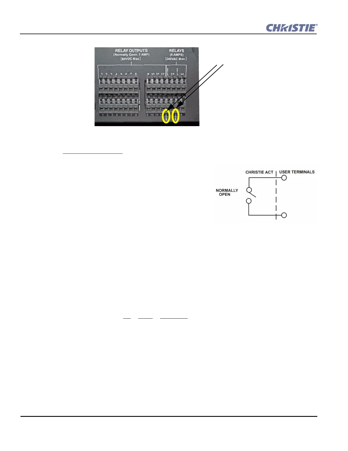
Figure 2-12 Relay Outputs
NOTE: Two connector pins are “NOT USED” as identified in Figure 2-12.
Refer to Section 6 Specifications
for more information.
Relay Output Features
• All contacts are normally open (N/O)
• Aligned vertically
• Contact closures
• Capacity: twelve 1 Amp and two 8 Amp
• Removable connector terminals for easy wire connection
NOTE: The two 8 Amp relays can be used to control primary
voltages.
2.4.7 USB
The USB is located on the front panel of the Christie ACT and is a deferred feature (Figure 2-1).
2.4.8 Ethernet
The Ethernet connector is located on the back panel of the Christie ACT (Figure 2-2). The Ethernet connection
is capable of 10/100 Base-T with 2 status LEDs. NOTE: Ethernet crossover cable is not required if connecting
directly to a PC.
Pin Signal Description
1 + Transmits data out
2 - Transmits data out
3 + Receives data in
4 Not connected
5 Not connected
6 - Receives data in
7 Not connected
8 Not connected
NOT USED
Figure 2-13 Relay Output