Section 3: Operation
Christie ACT User Manual 3-17
020-100129-05 Rev. 1 (02-2010)
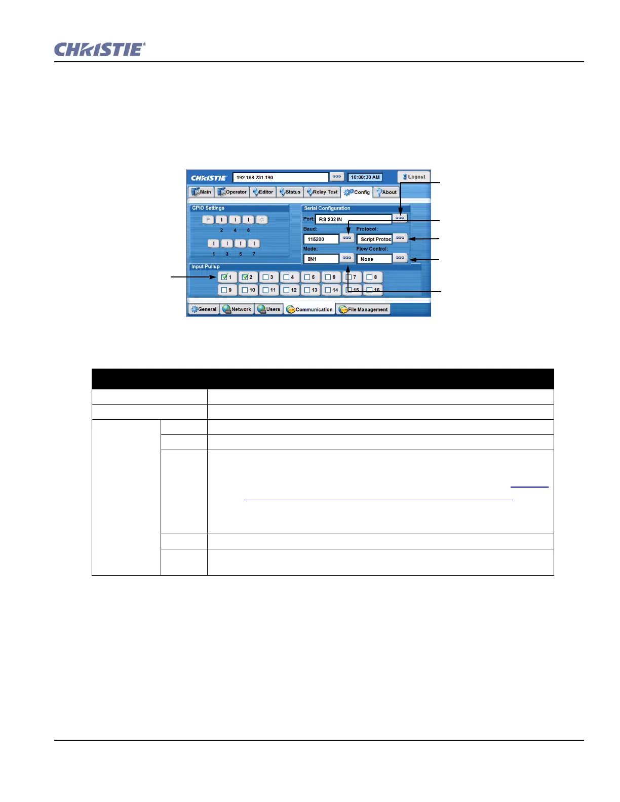
Config: Communication Tab
The Config: Communication tab provides the ability to configure the communication settings on Christie
ACT. Configure the direction of each GPIO by toggling each GPIO button between input (I) and output (O).
These changes instantly change the pin configuration of the device. You can also enable or disable the internal
input pull-up on the opto-isolated inputs by checking the appropriate boxes next to the inputs.
Table 3.8 Summary of Config: Communication Tab Options
CONFIG: COMMUNICATION TAB OPTIONS
GPIO Settings Click the buttons to toggle the direction of the specified pin.
Input Pull-up Input pull-ups allow internal pull-up connection to signal incoming source if required.
Serial
Configuration
Port Select the serial port to be configured from the list.
Baud Select the baud rate from the list to match the controlling device (ACT) baud rate.
Protocol Select the protocol from the list. Options include:
• Christie Protocol talks to the port in Christie formats, for example the com-
mands used when making a terminal connection. (NET+ETH0?) Refer to
Section
Configure the IP Address Using the Serial Port, on page 1-4.
• Raw Protocol does nothing and is designed to free the port for external uses.
• Script Protocol is used if you want to use input from that port in a script.
Mode Select the mode of the serial port.
Flow
Control
Select the type of serial flow to control the serial port selected.
Set baud rate to match the controlling
device (ACT): 115 200 maximum rate
for the selected serial port. NOTE:
Baud rate is the speed to
communicate at.
Select the serial port to be
configured.
Select the protocol for the selected
serial port.
Select type of serial flow to control
the serial port selected.
Select the mode of the selected serial
port.
Click inside a box to
enter a checkmark and
enable the desired input
pull up. NOTE: Pull ups
add power to the
selected input
connector. Deselect to
disable.
Figure 3-19 Config: Communication Tab