2-6 Christie ACT User Manual
020-100129-05 Rev. 1 (02-2010)
Section 2: Installation & Setup
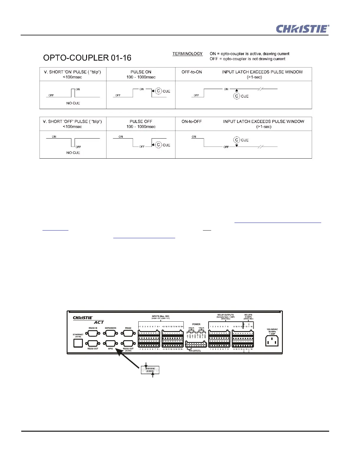
2.4.5 GPIO
The 9-pin GPIO male connector is located on the back panel of the Christie ACT. Refer to . It provides a
flexible method of interfacing a wide range of external input and output devices to Christie ACT, often so that
an event on one device automatically triggers an event on the other. The GPIO pins 2 to 4 and pins 6 to 9 are
for general purpose which are configured for input or output. Refer to the Config: Communication Tab, on
page 3-17. Each GPIO pin can be set to input or output but is not isolated. Power provided is 12V, which is
rated for 200 mA. Refer to Section 6 Specifications
for more information.
GPIO Features
• Configurable inputs/outputs for signalling between devices.
• Easy integration within an established control system.
• Ability to trigger user configurable script/actions on input events.
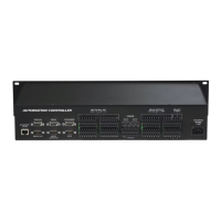
Figure 2-8 Rules for Opto-Inputs
Figure 2-9 GPIO
Pin 1
Pin 9