2-4 Christie ACT User Manual
020-100129-05 Rev. 1 (02-2010)
Section 2: Installation & Setup
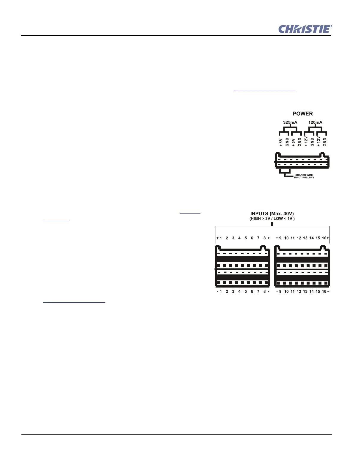
2.4.2 Power Out
The power outputs are isolated and separate from the main electronics. They are located to the left of the relay
outputs, facing the back panel (Figure 2-3). The Christie ACT accepts universal voltages, but includes a North
American plug. There are 4 output voltage rails, two 5V, 2W rails and two 12V, 2W rails. These can be
connected to the inputs/outputs as desired. A resettable (poly PTC type) fuse limits the total draw on these
rails. The pull-ups to 5V is shared with one of the isolated rails. Refer to Section 6 Specifications
for more
information.
Power Features
• 2x 5V outputs, 2x 12V outputs
• One 5V rail; shared with input pull-ups
• Current limited
• Internally fused
• Voltages can be connected in series for higher output voltages
• Removable connector terminals for easy wire connection
• Isolated, electronically, from the internal electronics
2.4.3 Power Input
For specifications pertaining to power input refer to Section
6.2 Power.
2.4.4 Inputs
The Inputs are located on the back panel of the Christie ACT.
There are two groups of 16 bi-directional inputs (32 terminals).
Both groups have the optional 5V pull-ups via software
control. The pull-ups are disconnected by default. Since a
double-stacked connector is used, the matching pairs of
terminals are arranged vertically. NOTE: For connection, the
top inputs are positive and the bottom are negative. Refer to
Section 6 Specifications
for more information.
Input Features
• Removable connector terminals for easy wire connection
• Configurable internal pull-ups are useful when power is unavailable from the user device (dry contacts, such
as un-powered relays, on the user device)
• 16 inputs, positive and negative input terminals
• +/- 30V Max. input voltage tolerance
• Optically-isolated from internal electronics
Figure 2-3 Power
Figure 2-4 Inputs