Section 2: Installation & Setup
Christie ACT User Manual 2-3
020-100129-05 Rev. 1 (02-2010)
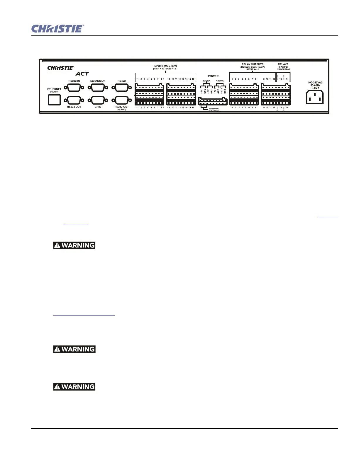
2.3 Back Panel
2.3.1 Back Display Panel
Communications
• Ethernet Management - Connect with an Ethernet switch for transmission of control and status com-
munications.
• RS232 - Connect with a server, PC or other device for serial communication.
• RS422 - Connect an RS422-compatible controller for unusually long-distance serial communication.
• GPIO -This is a digital GPIO. Connect the desired GPIO-compatible device here for integration of
Christie ACT with an established control system. Devices connected via GPIO can operate in tandem with
Christie ACT, or vice versa and is often used for automation of regularly scheduled events. Refer to Section
6.7 GPIO for input and output voltages.
AC Connector and Power Cord
1) The North American rated line cord is provided with each unit. Ensure that
you are using a line cord, socket and power plug that meets the appropriate local rating
standards. 2) Use only an AC power cord recommended by Christie. Do not attempt
operation if the AC supply and cord are not within the specified voltage and power range.
Use only the attachments and/or accessories recommended by Christie. Use of others may result in the risk of
fire, shock or personal injury.
Use the Christie ACT power cord for any installation. Plug into an appropriate wall outlet or use the
convenience outlet in the CP2000 pedestal. Christie ACT is rated for 100-240VAC. Refer to
Section 6 Specifications
for more information.
2.4 I/O Connections and Communications
Do not interrupt the Christie ACT while it is saving. This will interrupt any
active script!
2.4.1 Input/Output Connector Types
Primary voltages MUST be connected by Qualified Electricians only!
Figure 2-2 Christie ACT Back Panel