Verification
12.3.2 CR Mode Verification
This test module verifies if the programmed resistance complies with the specification in CR
Mode. The calculation of programmed resistance is voltage divided current. The voltage
(DMM (V)) passes through the input or measurement terminal of module. Also the voltage
(DMM (I)) goes through the current shunt, that is shunt current = DMM (I) voltage/shunt
resistance. If the voltage output and/or current limit setting of DC Power Supply are wrong, it
could trigger the OPP or OCP protection circuit of the Load module. Press ENTER to reset
the protection circuit.
The Electronic Load module imports constant resistance mode and uses CC circuit to
regulate the input. The Load input voltage is seen as the reference for current control. The
formula is I/V = 1/R.
V: The input voltage is the reference of D/A.
I: It is the controlled parameter to decide the resistance.
1/R: It is the conductance, reciprocal of resistance.
The specification of CR mode accuracy is as the conductance specified. The effect on the
programmed resistance value is not linear over the resistance range, because the resistance
is a reciprocal conductance. The Electronic Load is designed following the application of the
high current in CR mode, thus when there is a need for large resistance, the Load will read the
voltage and current to calculate the actual resistance and adjust the settings to improve the
accuracy. The example below illustrates the error in CR mode in the worst case.
Example 1: 0.005 ohm to 20 ohm range (Model 63201A, CRL)
The accuracy of this range is specified as 0.104S + 0.35%,
if 0.1 ohm has been programmed, the actual resistance will be
Conductance: 10+(0.104+10× 0.35%) to 10−(0.104+10× 0.35%)
Resistance: 0.098629 to 0.10141
if 0.05 ohm has been programmed, the actual resistance will be
Conductance: 20+(0.104+20× 0.35%) to 20−(0.104+20× 0.35%)
Resistance: 0.049569 to 0.050439
Connect the DC Load, DC Power Supply, DMM and Current Shunt as Figure 12-1 shows. Use
DMM (V) to measure the voltage passing through the module input terminal and the DMM (I)
passing through the shunt current measurement port. Be careful when doing the connection
so that the contact voltage drop will not affect the reading or use remote sense to get the
UUT’s voltage. The load resistance = DMM (V)/shunt current.
12.3.2.1 Checking for High ohm Range
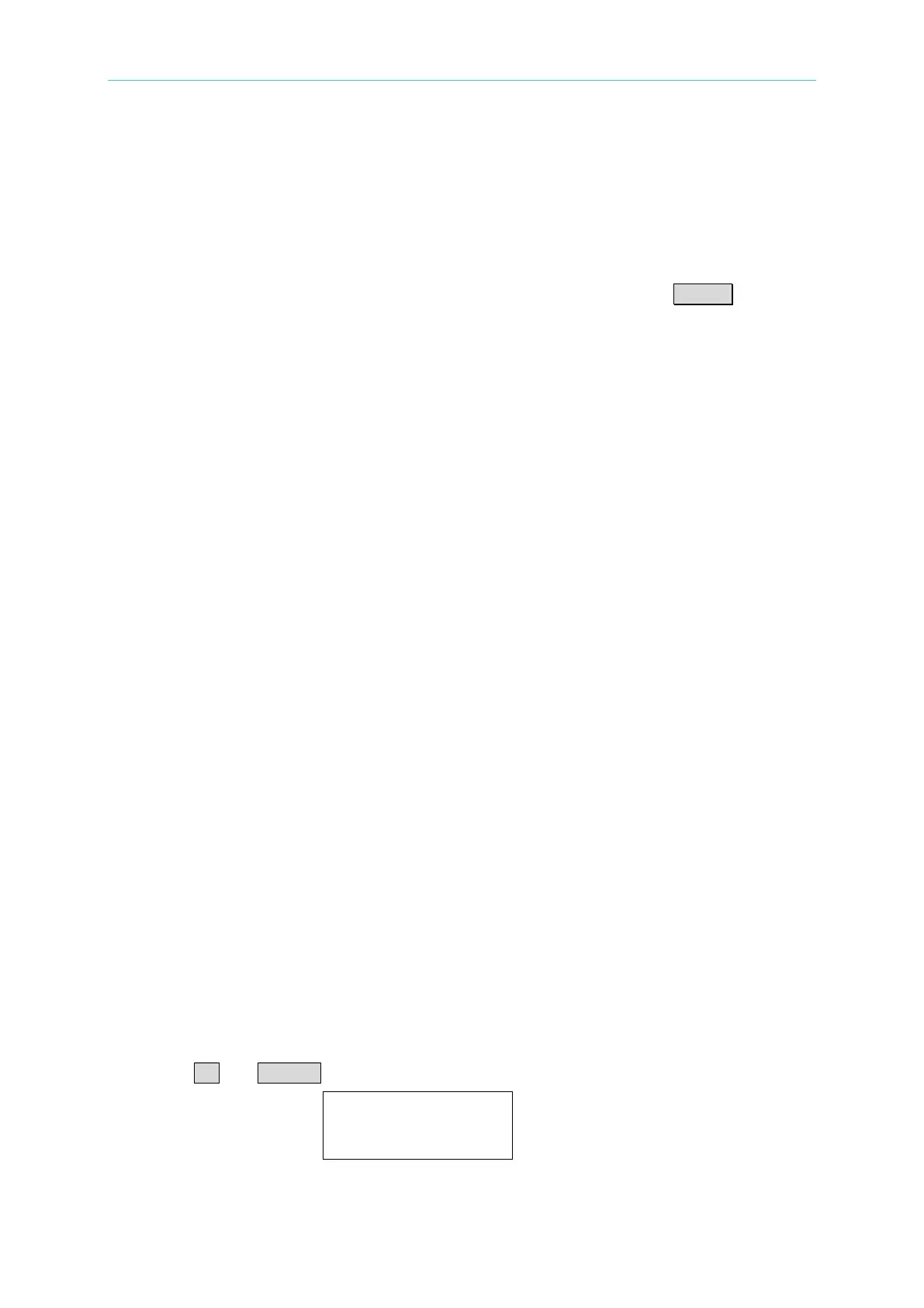
A. Press CR and RANGE to select CRH. The screen shows:
CRHA: 2.000Ω
CRHB:
1.000Ω

 Loading...