TRANSTIG 170Pi
Manual 0-5242 6-11
TROUBLESHOOTING
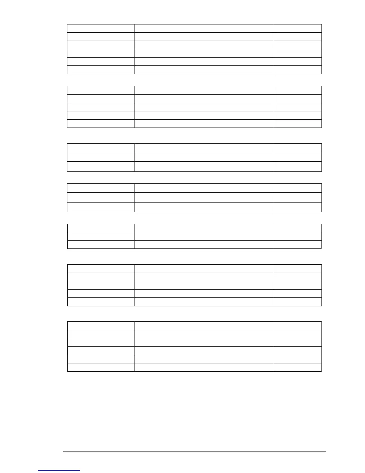
DY1 Header Pin Pin function Signal
1 +24V (solenoid positive) 24 VDC
2 0V 0 VDC
3 No connection n/c
4 No connection n/c
5 No connection n/c
Table 6-12: DY1 Header pin function
FJ/QF Header Pin Pin function Signal
1 No connection n/c
2 +24V 24 VDC
3 +24V 24 VDC
4 0V 0 VDC
Table 6-13: FJ/QF Header pin function (not used)
RX Header Pin Pin function Signal
1 Inrush Resistor
2 Inrush Resistor
Table 6-14: RX Header pin function (connects to Inrush Resistor)
JC Header Pin Pin function Signal
1 +5V +5 VDC
2 PFC OK signal, 5V = PFC OK
Table 6-15: JC Header pin function (connects to PFC header on control PCB)
HF220V Header Pin Pin function Signal
1 240VAC active 240VAC
2 240VAC neutral 0 VAC
Table 6-16: HF220V Header pin function (connects to 220V header on HF PCB)
GUNIN Header Pin Pin function Signal
1 Trigger 8 pin socket, pin 2
2 Remote Amps Pot, 8 pin socket, pin 5
3 Remote Amps Pot, 8 pin socket, pin 6
4 Trigger 8 pin socket, pin 3 0 VDC
Table 6-17: GUNIN Header pin function (connects to 8 pin remote socket)
GUNOUT Header Pin Pin function Signal
1 Trigger 8 pin socket, pin 3 0 VDC
2 Trigger 8 pin socket, pin 2
3 Remote Amps Pot, 8 pin socket, pin 5
4 Remote Amps Pot, 8 pin socket, pin 6
5 Trigger 8 pin socket, pin 3 0 VDC
Table 6-18: GUNOUT Header pin function (connects to GUN header on control PCB)