TRANSTIG 170Pi
TROUBLESHOOTING 6-12 Manual 0-5242
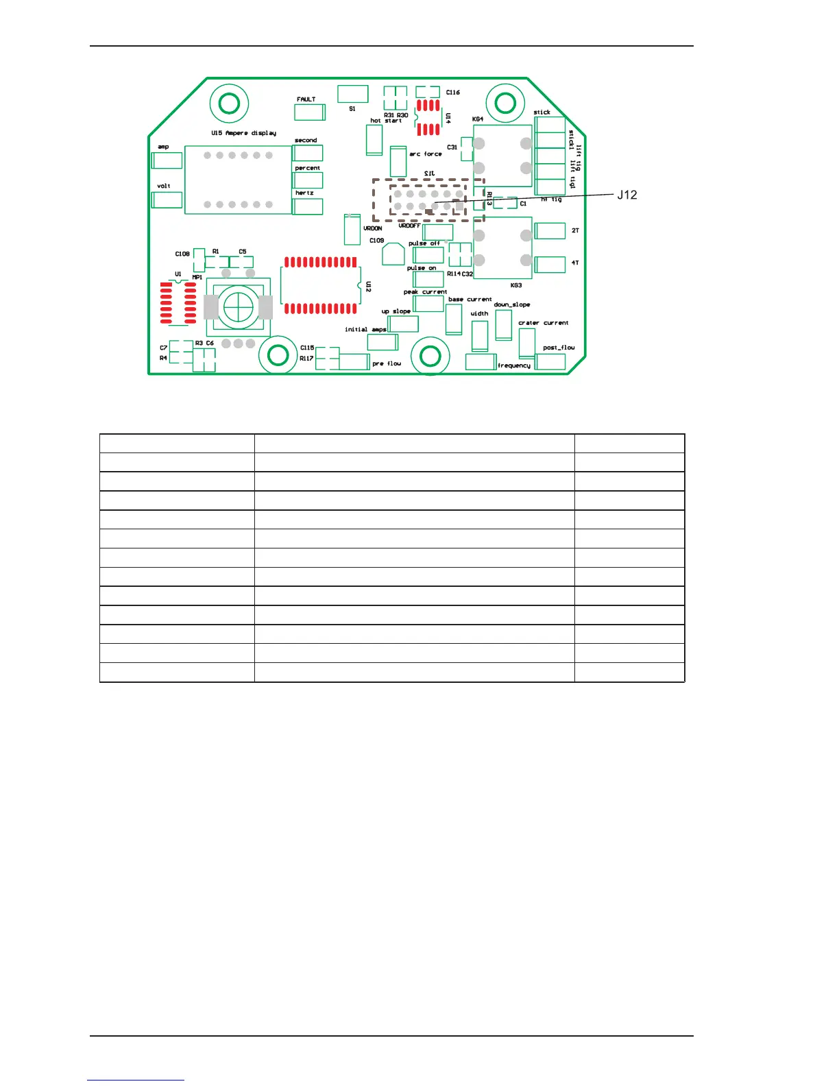
2. Display PCB
Art # A-11818
Figure 6-8: Display PCB Connectors
J12 Header Pin Pin function Signal
1 Serial display data (LOAD)
5 VDC digital
2
Serial display data & eprom (D-IN)
5 VDC digital
3
Serial display data (CLK)
5 VDC digital
4
Serial display eprom (D-OUT)
5 VDC digital
5
DeadMan Switch (5V in DeadMan mode)
5 VDC digital
6
Encoder Output “A” (pulse output)
5 VDC digital
7
Encoder Output “D” (button)
5 VDC digital
8
Encoder direction
5 VDC digital
9
2T/4T pushbutton (0V when button pushed)
5 VDC
10
MODE pushbutton (0V when button pushed)
5 VDC
11
0V
0 VDC
12
5 VDC
5 VDC
Table 6-19: J12 Header pin function (connects to MB header on control PCB)