DSB75 Development Support Board Rev. B1 Hardware Description
Confidential / Released
DSB75_hd_v12 Page 11 of 96 2008-08-26
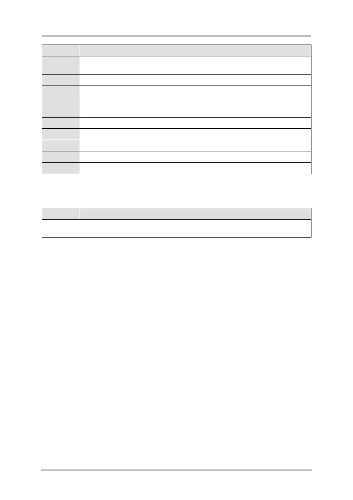
Chapter What is new
5.2 Table 33: added jumpers X122, X203, X204, X206, X420, X421 X562, X600 and
footnotes 2, 3. Added figure: “Location of jumpers”.
6 Added mounting description and figure: “Mounting GSM module onto the DSB75”.
7.1 Deleted constraints: “Start-up by DTR0 toggling is only effective if the USB host is not
active. Start-up by plugging the USB cable is only effective if the RS-232 lines are
deactivated by the host application (e.g. if the terminal program is closed). In later
releases of DSB75 this problem will be solved.” Modified figure: “Turn on circuit”.
7.2 Added information about automatic restart of the module.
8 Updated technical data.
8.1 More detailed list of cable requirements.
9.2 Modified figures “Schematic sheet1” … “Schematic sheet7”
9.3 Modified figure: “Floor plan top side”; added figure: “Floor plan bottom side”
Preceding document: ”DSB75 Development Support Board Hardware Description", v01
New document: ”DSB75 Development Support Board Hardware Description", v02
Chapter What is new
Completely revised and updated all chapters and technical specifications. Added new chapters and
appendix.