DSB75 Development Support Board Rev. B1 Hardware Description
Confidential / Released
DSB75_hd_v12 Page 27 of 96 2008-08-26
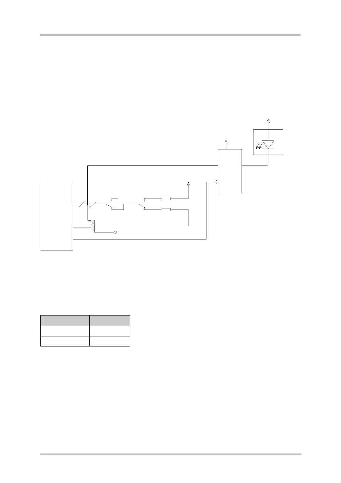
3.3 GPIO Lines
The DSB75 board has 10 GPIO facilities (see Figure 7). Which of them are used depends
on the type of GSM module and the software configuration.
If the GPIO lines are configured as input, the level may be set to 0 or 1 by S460 - S469.
The GPIO lines can be connected to measurement equipment or to an external host
application via the test pin X101.
Figure 7: GPIO circuit
GPIO status is indicated by LEDs (for GPIOs 1-6 and 9-10).
Table 8: LED indication of GPIO status
GPIO level LED status
0 (low) on
1 (high) off
8x LED
Buffer
Enable
S450
S451
S452
S453
S454
S455
S458
S459
SD_DO(GPIO1)
SD_D1(GPIO2)
SD_D2(GPIO3)
SD_D3(GPIO4)
SD_CLK(GPIO5)
SD_CMD(GPIO6)
SD_DET(GPIO7)
SD_WP(GPIO8)
RXD2_GPIO9
TXD2_GPIO10
8x10K
S460
S461
S462
S463
S464
S465
S468
S469
D450, D221
V450 (GPIO1; SD_D0 )
V451 (GPIO2; SD_D1)
V452 (GPIO3; SD_D2)
V453 (GPIO4; SD_D3)
V454 (GPIO5; SD_CLK)
V455 (GPIO6; SD_CMD)
V242 (GPIO9)
V243 (GPIO10)
Test points
X101
B2B
X100
PWR_IND
8
1
3
1
3
VDD
3V0
3V0
8x10K
8