DSB75 Development Support Board Rev. B1 Hardware Description
Confidential / Released
DSB75_hd_v12 Page 50 of 96 2008-08-26
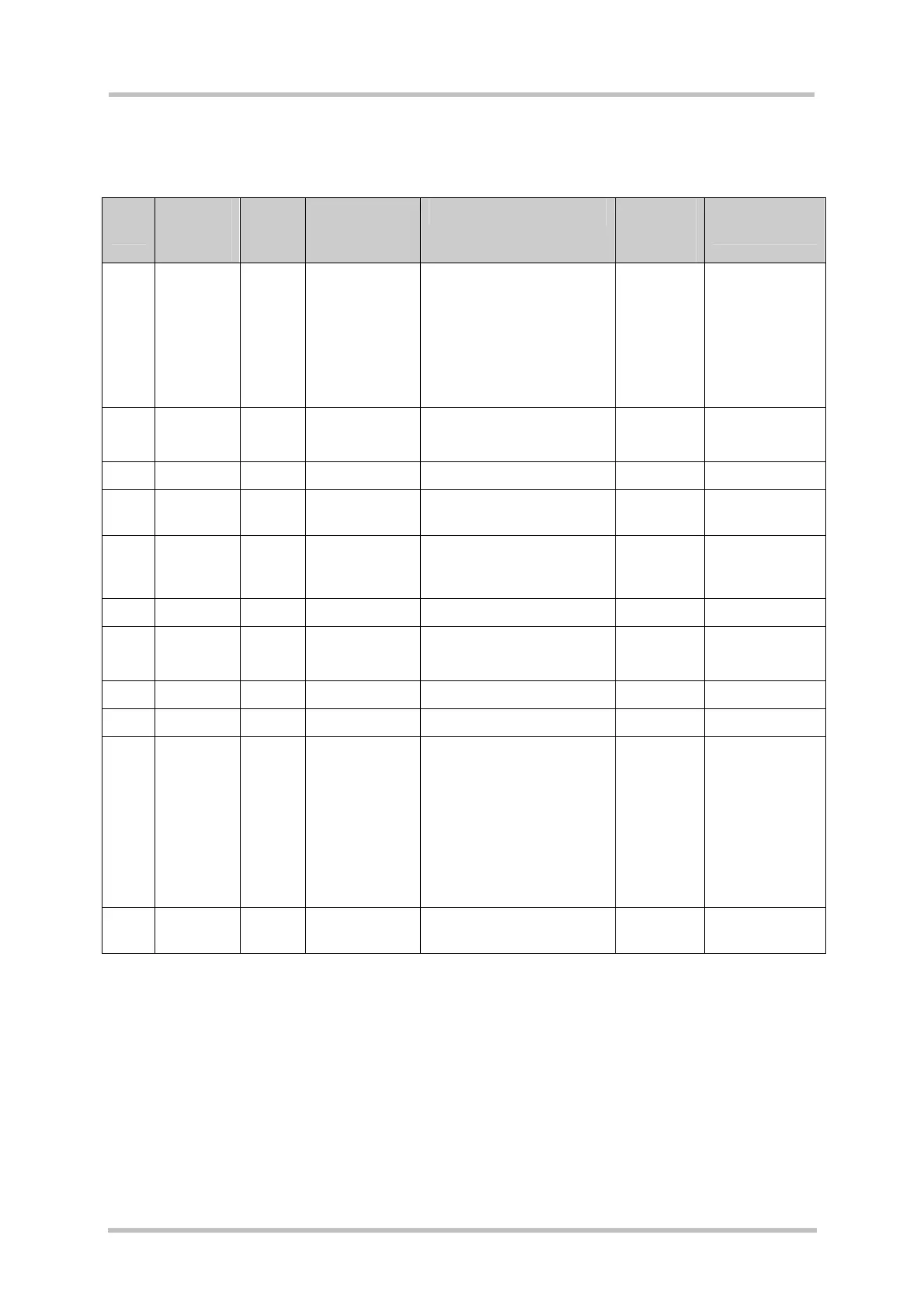
3.10.1 SD 4 Bit Mode
Table 19: Pin assignment of SD card interface X301 (SD 4 bit mode)
X301
pin
X301
signal
name
I/O Description Remark X100
signal
name
Configuration
switches
1 CD/DAT3 I/O Data line bit 3,
Card detect
Card detect at power on:
0 or open = card removed
1 or 50k pull-up = card
inserted
Note: This is no removal
detection during card
operation!
SD_D3 S453:1
S301:1
2 CMD O Command /
Response
SD_CMD S455:1
S303:1
3 VSS1 Supply Ground GND
4 VDD Supply Supply
voltage
2.9V
5 CLK O Clock 25.4kHz …13MHz
(depends on SW
performance)
SD_CLK S454:1
S305:1
6 VSS2 Supply Ground GND
7 DAT0 I/O Data line bit 0 SD_D0 S450:1
S307:1
8 DAT1 I/O Data line bit 1 SD_D1 S451:1
9 DAT2 I/O Data bus bit 2 SD_D2 S452:1
10 CD I Card
detection
0 = card inserted
1 = card removed
Note: On each edge an
interrupt will be
generated. Removing the
card will stop its operation
before disconnecting it.
SD_DET
11 WP I Write protect
detection
0 = unlocked
1 = locked
SD_WP