DSB75 Development Support Board Rev. B1 Hardware Description
Confidential / Released
DSB75_hd_v12 Page 13 of 96 2008-08-26
1.3 Scope of Delivery
1.3.1 Standard package DSB75 Development Support Board
Table 1: Standard package DSB75 Development Support Board
Quantity Description
1 DSB75 Development Support Board
1 MiniMag antenna (850 MHz – 1990 MHz)
2 RF adapter cable 150mm (Hirose – Hirose)
1 Votronic handset
2 Hexagon nuts (DIN 934 – ISO 4032)
2 Screws M2 (DIN 84 – ISO 1207)
2 Insulating spacers for M2, self-gripping
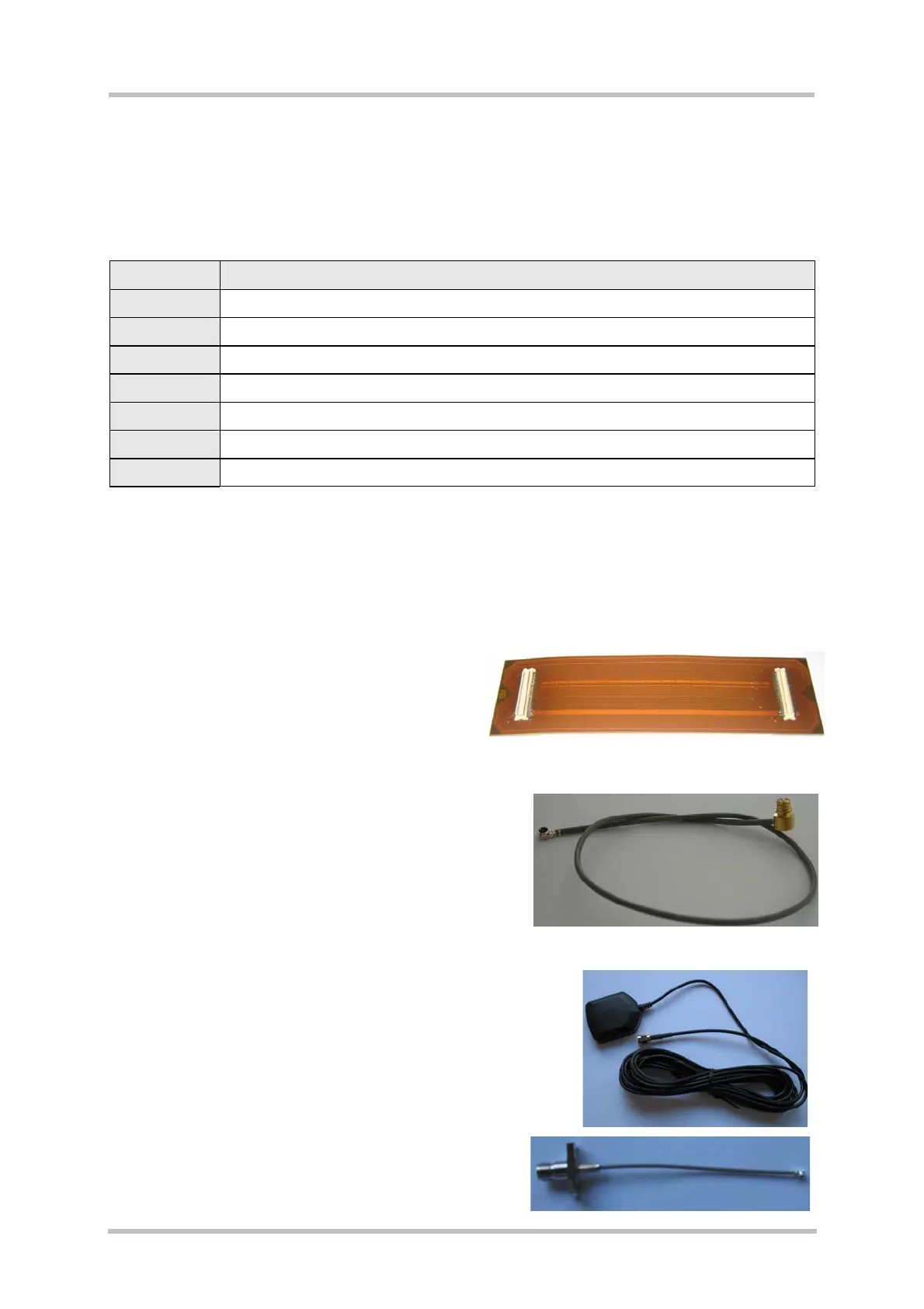
1.3.2 Product specific accessories
Some products require additional cables which are not part of the standard DSB75 package,
but are supplied separately:
AC65, AC75, XT65, XT75:
- Flat flexible cable (100 mm) for connecting
the module to the board-to-board connector
located on the DSB75 board.
AC65, AC75:
- Special GSM adapter cable (200 mm) with Hirose
U.FL-LP-066 and Rosenberger SMP 19K202-270
connectors.
XT65, XT75:
- Active GPS antenna
- Special GPS adapter cable (100 mm) with Hirose
connector and female SMA connector to be connected
to the module and to the active GPS antenna.