DSB75 Development Support Board Rev. B1 Hardware Description
Confidential / Released
DSB75_hd_v12 Page 21 of 96 2008-08-26
Figure 3: Block diagram
2.5 Interface Overview
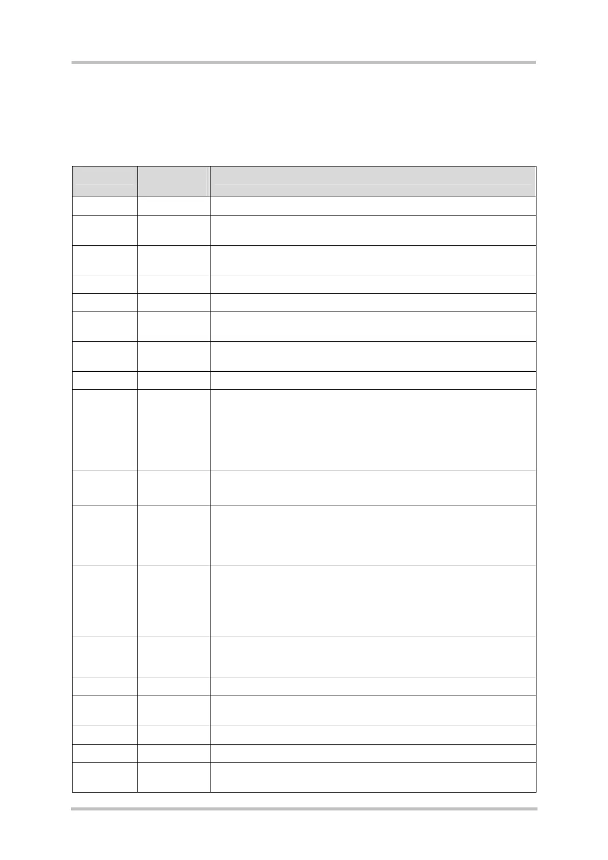
Table 4: Interfaces of the DSB75
Interface Reference
number
Description
IGT S421 Ignition push button
Emergency
reset
S420 Emergency reset push button
Handset X502 Audio interface 1 (4-pin western jack). Intended for connecting a
handset.
SIM X503 SIM card holder
RF X506 RF signal (SMA connector)
Green LED V431 DSB ON. Power LED that indicates the operating voltage for the
DSB75.
Yellow LED V430 Module ON. Power LED that indicates the operating voltage for the
GSM module.
SD card X301 SD card holder
Charger,
Headset,
Carkit
X700, X701 Two different functions provided by the same connector (Lumberg
connector):
a) Input for plug-in charger
b) Audio 2 interface for headset or speakerphone
X700 for old, X701 for new accessories.
9V
GND
X400 (red)
X401 (black)
Supply voltage nominal +9V. Connectors used to attach a laboratory
PSU.
COM1 X201 Serial interface 1 (9-pin SubD connector). RS-232C interface with 8
data and modem control lines. Intended for GPRS data, circuit
switched data, multiplexed data, AT commands.
Connects to the module’s serial interface ASC0.
COM2 X202 Serial interface 2 (9-pin SubD connector). RS-232C interface with 2
data and 2 modem control lines: TXD1 and RXD1 plus RTS1 and
CTS1 for hardware handshake. Intended for GPRS data and AT
commands.
Connects to the module’s serial interface ASC1.
COM3 X205 Debug interface (9-pin SubD connector). RS-232C interface with
2 data lines: TXD2 and RXD2.
Connects to the module’s serial interface ASC2 (for internal use only).
USB B X110, X111 USB device interface (type B receptacle)
GSM
module
X100 80 pole board-to-board connector for GSM module
RF X505 RF connector for connecting GSM module via RF cable
Battery X602 Battery connector
Test points X101, X102 80 test pins (80 pole dual strip
1
); 1:1 connection to B2B connector
X100, Terminal for GPIOs, ADCn_IN lines