DSB75 Development Support Board Rev. B1 Hardware Description
Confidential / Released
DSB75_hd_v12 Page 30 of 96 2008-08-26
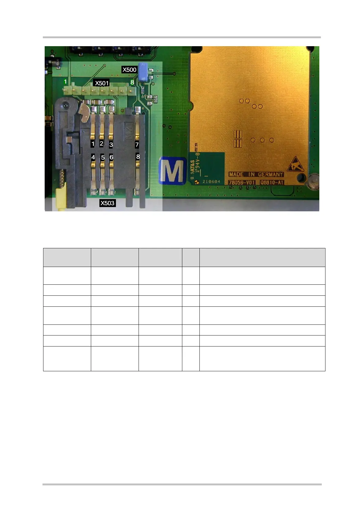
Figure 10: Pin location of the Molex SIM card holder and test pins
Table 10: Pin assignment – SIM card holder X503 and test pins X501
Pin number on
holder X503
X501 test
points
Signal name I/O Function
1 1 VSIM O Supply voltage U = 2.93V (typ.) or 1.8V for
SIM card, generated by the module.
2 2 CCRST O Chip card reset, prompted by the module
3 3 CCCLK O Chip card clock
4,8 4, 5, 7 CCGND - Separate ground line for the SIM card to
improve EMC
5 - CCVPP - Not connected
6 6 CCIO I/O Serial data line, bi-directional
7 8 CCIN I Chip card detection
0 = Chip card drawer is inserted
1 = Chip card drawer is not inserted