DSB75 Development Support Board Rev. B1 Hardware Description
Confidential / Released
DSB75_hd_v12 Page 29 of 96 2008-08-26
3.4 SIM Card Interface
The DSB75 has an integrated SIM card interface. An appropriate SIM card (3V or 1.8V) is
required to start the GSM module. The SIM card holder X503 placed on the DSB75 is from
type Molex. To open the card holder simply press the yellow pin.
In parallel to the SIM card holder X503, the test points X501 are connected, e.g. for SIM test
equipment.
In series to the recognition switch (holder pins 7 and 8) there is a jumper X500 connected. It
must set for normal operation and may be used for testing the SIM card detection ability
from a remote device.
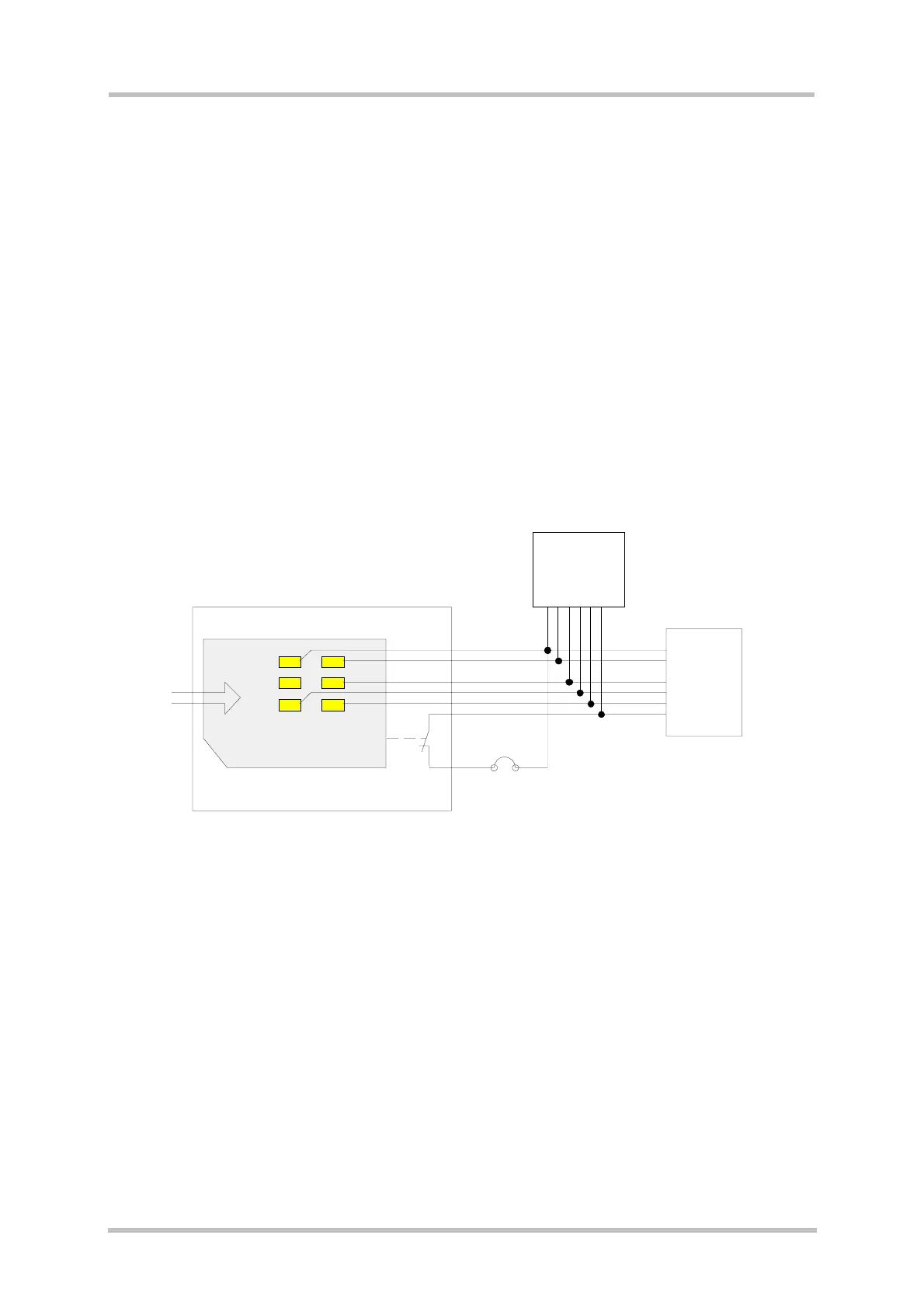
Figure 9 shows the simplified interface schematic.
The pin location of the SIM card holder and SIM test pins is shown in
Figure 10.
The pin assignment is given in
Table 10.
VSIM
CCRST
CCIO
CCCLK
CCIN
4
1
2
6
3
7
8
CCGND
VSIM
CCRST
CCIO
CCCLK
CCIN
CCGND
B2B
X100
X501
X503
X500
21
17
19
18
16
20
4,5,7
1
2
6
3
8
SIM test pins
SIM card
Card holder
Figure 9: SIM card interface