DSB75 Development Support Board Rev. B1 Hardware Description
Confidential / Released
DSB75_hd_v12 Page 52 of 96 2008-08-26
3.10.3 SPI Bus Mode
This interface is an option and an alternative to the ASC1 and SPI2 interfaces. It has to be
reconfigured via AT commands as SPI bus mode SD card interface. For further information
refer to section
3.11.
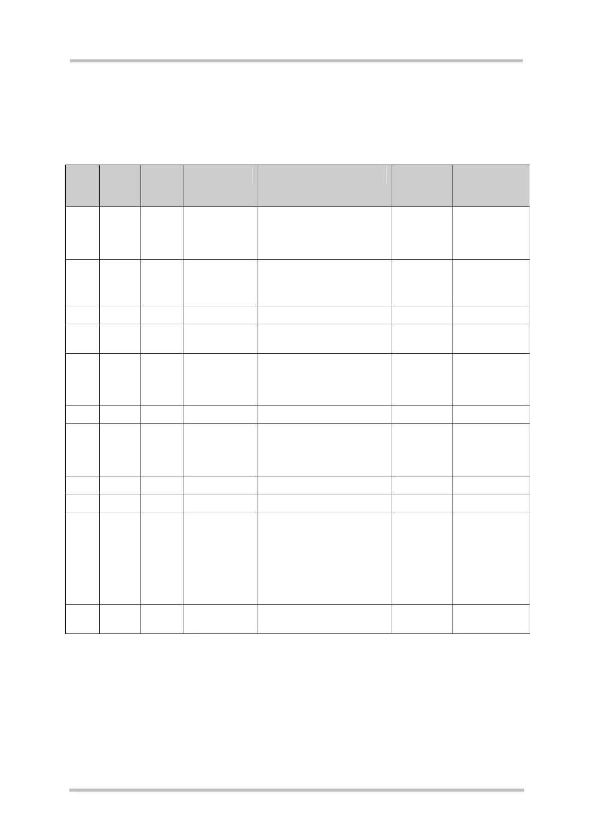
Table 21: Pin assignment of SD card interface X301 (SPI bus mode)
X301
pin
X301
signal
name
I/O Description Remark X100
signal
name
Configuration
switches
1 CS O Chip select Active low TXD1 S300:3
S301:3
S453:3
2 DI I Data input Data out (DO) at SD card
side
CTS1 S306:3
S307:3
S450:3
3 VSS1 Supply Ground GND
4 VDD Supply Supply
voltage
2.9V
5 SCLK O Clock up to 3.25MHz RTS1 S304:3
S305:3
S454:3
6 VSS2 Supply Ground GND
7 DO O Data output Data in (DO) at SD card
side
RXD1 S302:3
S303:3
S455:3
8 - Not used
9 - Not used
10 CD I Card
detection
0 = card inserted
1 = card removed
Note: On each edge an
interrupt will be generated.
Removing the card will stop
its operation before
disconnecting it.
SD_DET
11 WP I Write protect
detection
0 = unlocked
1 = locked
SD_WP