DSB75 Development Support Board Rev. B1 Hardware Description
Confidential / Released
DSB75_hd_v12 Page 41 of 96 2008-08-26
3.7 Digital Audio Interface
The Digital Audio Interface (DAI) can be used for acoustic approval or for transferring PCM
digital audio data between the GSM module and the customer application. The DAI of the
GSM module is designed for use with a codec or a DSP.
The DSB75 provides different facilities to connect the GSM module and the system
environment: the 10 pin DAI connector X703 and the pin headers (X101, X102).
Note: The DAI signals DAI0… DAI6 are connected to the signals USC0… USC6.
Table 16
shows the pin assignment of the 10 pin DAI connector X703.
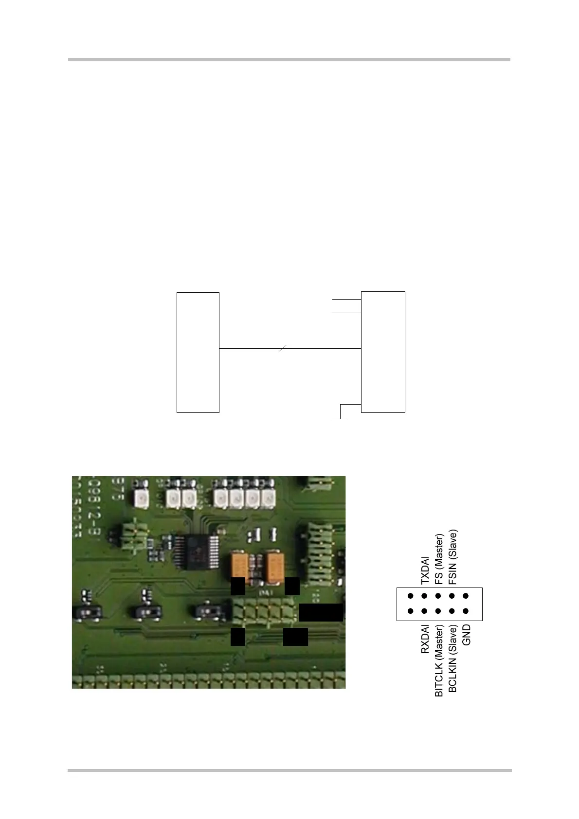
Figure 18 contains a simplified interface schematic. Figure 19 shows the location and the pin
assignment of the DAI connector. Electrical characteristics are specified in section
8.
USC0
USC1
USC2
USC3
USC4
USC5
USC6
DAI0
DAI1
DAI2
DAI3
DAI4
DAI5
DAI6
26
25
24
23
22
13
15
3
4
5
6
7
8
9
5V0
VDD
GND
5V0
2.9V
1
2
10
7
X100
X703
2x5 pin
B2B
Figure 18: DAI interface
X703
2
1 9
10
1
2
9
10
Figure 19: Location and pin assignment of the DAI connector X703