DSB75 Development Support Board Rev. B1 Hardware Description
Confidential / Released
DSB75_hd_v12 Page 23 of 96 2008-08-26
3 Description of DSB75 Interfaces
3.1 GSM Module Interface (Board-to-Board Connector)
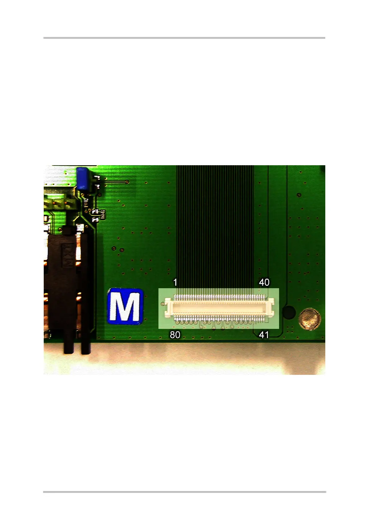
The Molex board-to-board connector X100 on the DSB75 is an 80-pin double-row
receptacle.
Figure 4 shows the names and positions of the pins on the DSB75. The pin
allocation is identical to the GSM module, but pin names may be different.
Several pins have multiple functions depending on the type of GSM module and a variety of
alternate configurations.
Figure 4: Pin assignment of the B2B connector