DSB75 Development Support Board Rev. B1 Hardware Description
Confidential / Released
DSB75_hd_v12 Page 7 of 96 2008-08-26
0 Document History
Preceding document: "DSB75 Development Support Board Rev B1 Hardware Description", v11
New document: "
DSB75 Development Support Board Rev. B1 Hardware Description" Version v12
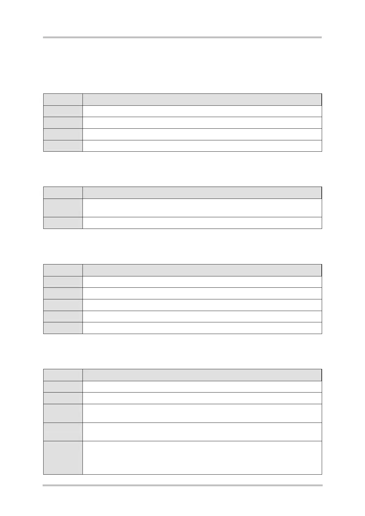
Chapter What is new
1.1 Added further supported products.
1.3 Added notes on product specific cables.
3.7 Further detail on pin assignment of DAI connector X703 and Master/Slave mode.
6 Added notes on product specific mounting requirements.
Preceding document: "DSB75 Development Support Board Rev B1 Hardware Description", v10
New document: "
DSB75 Development Support Board Rev. B1 Hardware Description" Version v11
Chapter What is new
1.3 Deleted antenna adapter cable in Table 1 .
Added note on extra cables needed for AC75 only.
6 Added note for AC75 only.
Preceding document: "DSB75 Development Support Board Rev B1 Hardware Description", v09
New document: "
DSB75 Development Support Board Rev. B1 Hardware Description" Version v10
Chapter What is new
3.5 Replaced Figure 11
3.9 Table 3: Added remark on recommended pull-up resistor.
3.12 Updated Figure 31 and Table 24 (changed X101/34 to X101/33)
8 Updated min/typical values of I²C pull-up resistor.
9.1 Added ordering number for DSB75.
Preceding document: "DSB75 Development Support Board Rev B1 Hardware Description", v08
New document: "
DSB75 Development Support Board Rev. B1 Hardware Description" Version v09
Chapter What is new
2.4 Figure 3: Corrected specification of GPIO7 and GPIO8
3.3 Figure 7, Table 9: Corrected descriptions of pins 6 and 8 (X100).
3.12 “Figure 31: Analog interface” and “Table 24: Pin assignment of the analog interface”
corrected names of analog input 1and analog input 2
5.1 Table 32: Overview of switch positions – corrected descriptions of switches S456 and
S457
9.2 Figure 49, Figure 51, Figure 54 and Figure 55 – changed names of the following
signals:
• AD1_IN -> ADC1_IN
• AD2_IN -> ADC2_IN