DSB75 Development Support Board Rev. B1 Hardware Description
Confidential / Released
DSB75_hd_v12 Page 16 of 96 2008-08-26
2 General Overview
2.1 Key Features at a Glance
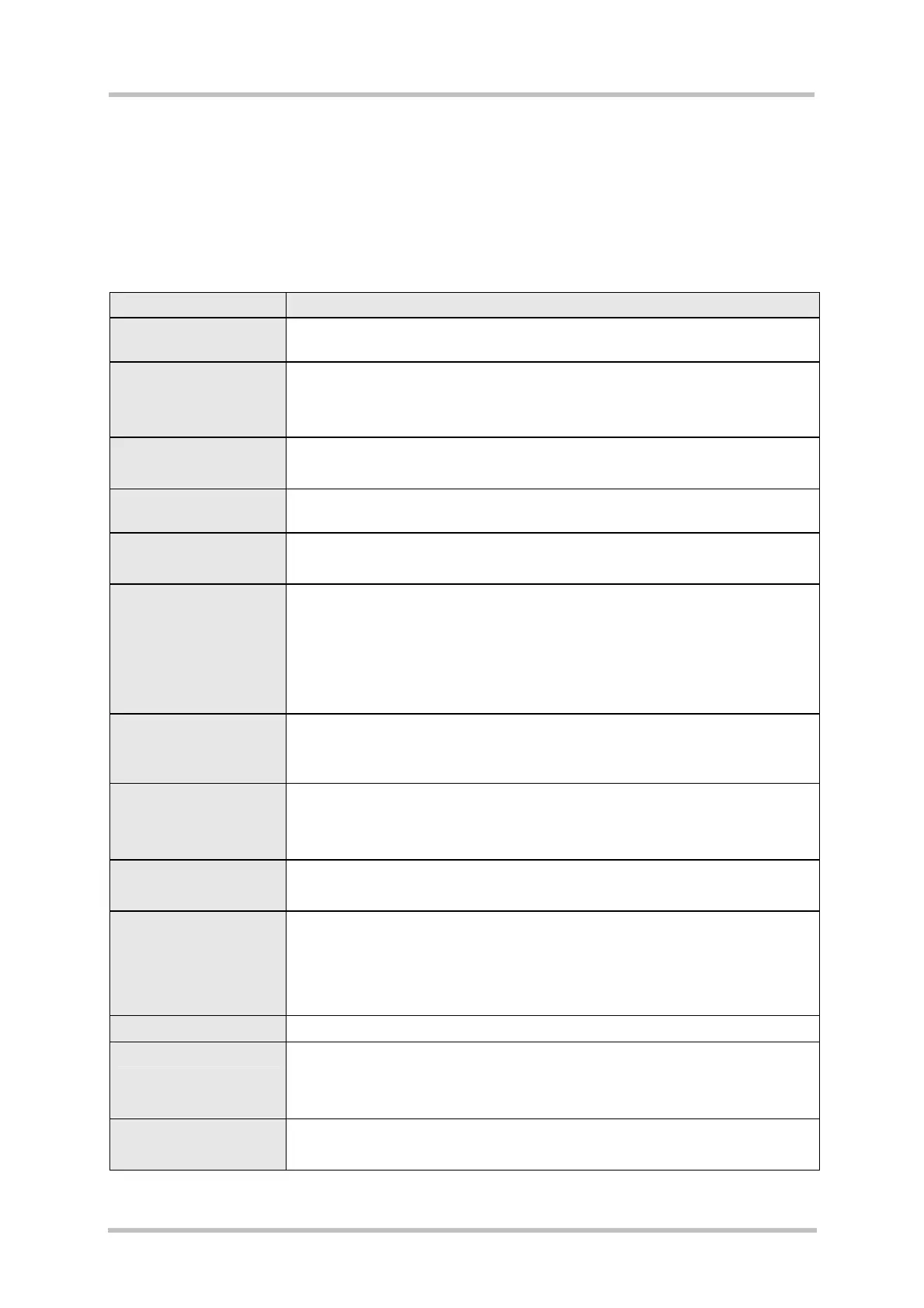
Table 3: Key features
Feature Implementation
GSM module interface
• Direct connection and mechanical fixing of GSM module via 80-pin
board-to-board connector and screws.
Power supply
• Laboratory PSU (9V…15V)
or
• Battery 3.3V…4.5V
Battery charging
• Implemented charging circuit (FET)
• Operation with plug-in charging adapter
Antenna interface
• Integrated connection between module’s Hirose connector and SMA
connector
SIM interface
• SIM card connector with front tray loading and card detection
• Supported SIM cards: 3V and 1.8V
SD Card interface
• SD card connector with front slot, card detection indication and write
protection indication
• Supply voltage: 2.9V
• Supported modes:
SD mode or
SPI mode
Audio interfaces
• Two analog audio interfaces (both with microphone supply) for
connecting a handset, headset or speakerphone.
• One digital audio interface (DAI)
I²C interface
• Host mode
• Supports 3V or 5V devices (configurable)
• Connected I²C EEPROM (128kBit) with adjustable addresses
SPI interface
(option)
• Two interfaces to be used alternatively to other interfaces
• Host mode
Serial interfaces
• Three RS-232C interfaces:
COM1 - serial interface for data communication
COM2 - serial interface for control purposes
COM3 - serial interface for debug purposes
• Max. baud rate: 460800 bps
USB interfaces
• USB 1.1 Full Speed (12 Mbit/s) device interface at B receptacle (default)
GPIOs
• 10 GPIOs at pins
• Switchable pull-up/down resistors (for 8 GPIOs)
• LED signaling (for 8 GPIOs)
ADC inputs
• 2 analog inputs
• Switchable loop with DAC output at each line