DSB75 Development Support Board Rev. B1 Hardware Description
Confidential / Released
DSB75_hd_v12 Page 66 of 96 2008-08-26
3.14.5 Adjusting the V
BATT+
Supply Voltage for the GSM Module
For test purposes, the V
BATT+
voltage supplied to the GSM module can be adjusted using
jumpers and variable resistors.
The jumpers X410 and X411 serve to set the V
BATT+
voltage range, and the variable resistors
R414 and R415 are used to adjust the supply voltage within the selected range. Therefore,
first set the range (lower limit or normal). Then turn the screw of the associated resistor
R414 or R415 to reduce or increase the desired voltage, while measuring the module’s input
voltage at its test points BATT+ and GND. Take into account that voltage drops and ripples
may occur. The maximum voltage is set only via the jumpers, it cannot be adjusted via the
resistors.
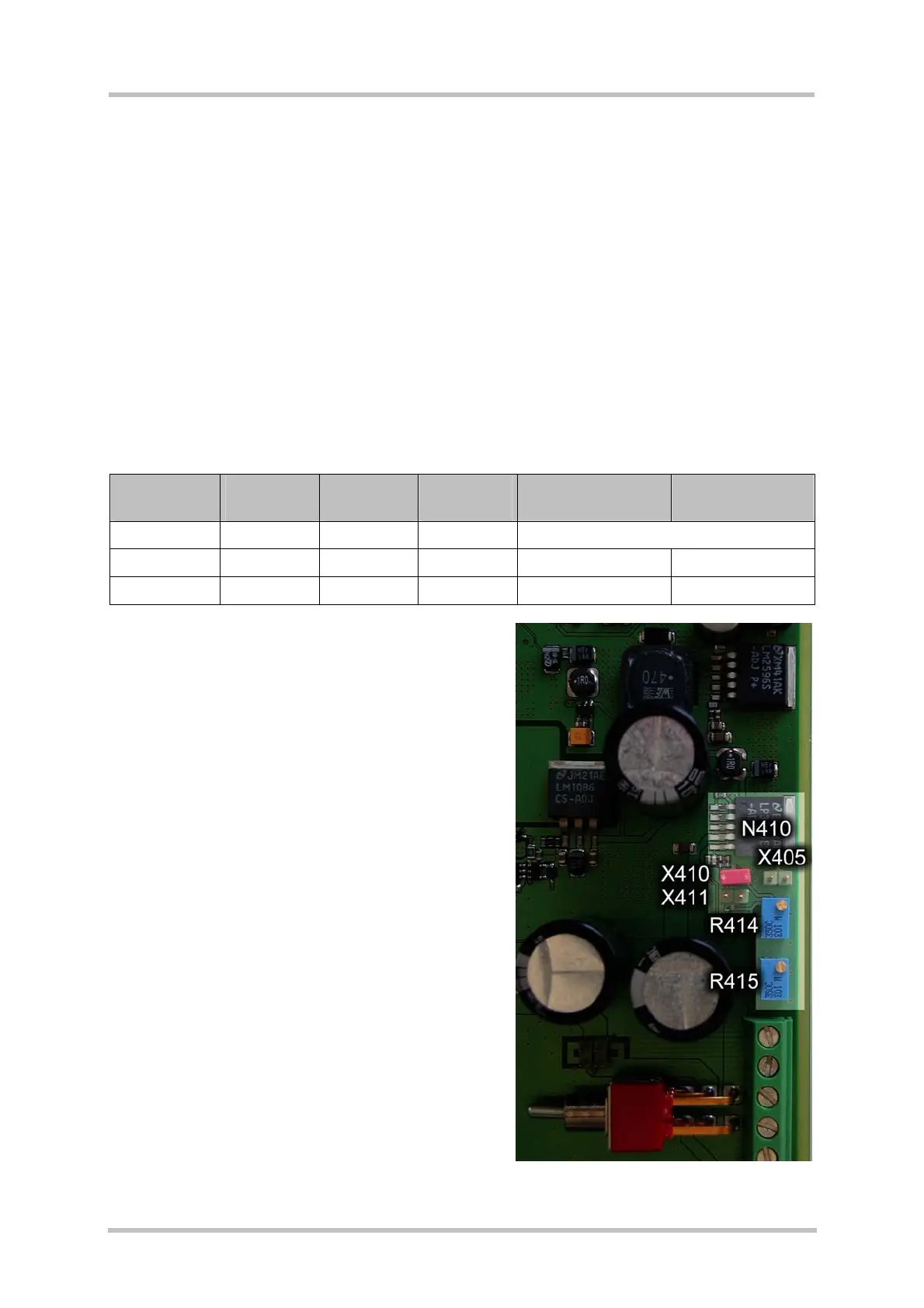
Figure 39 shows the location of the jumpers and variable resistors on the DSB75. The
settings for adjusting the supply voltage of the GSM module are described in
Table 31.
Table 31: Adjusting BATT+ voltage (3V3_4V5)
Voltage
type
Jumper
X410
Jumper
X411
Variable
Resistor
Voltage range Default setting
Upper limit closed closed --- 4.5V +-5% fixed
Normal closed open R415 2.85V. to 4.5V 4.1V +- 5%
Lower limit open closed R414 2.85V. to 4.5V 3.5V +- 5%
Figure 39: Location of jumpers and resistors for adjusting
BATT+ voltage (3V3_4V5)