DSB75 Development Support Board Rev. B1 Hardware Description
Confidential / Released
DSB75_hd_v12 Page 62 of 96 2008-08-26
3.14.2 Power Supply for DSB75 and GSM Module
The voltage provided by the 9V…15V PSU generates all supply voltages required for the
DSB75 and the connected GSM module when battery operation is disabled.
The output power of the laboratory PSU has to satisfy the SELV requirements in accordance
to EN 60950.
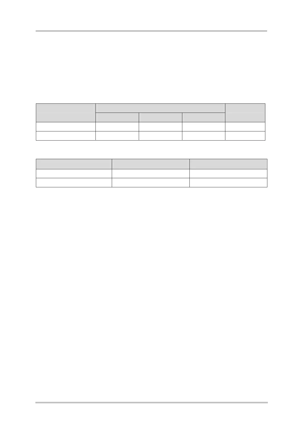
Table 26: Recommended specification of the laboratory PSU
Value Parameters
Min. Typical Max.
Unit
Output voltage 8.5 12 15.5 V
Output current 1.5 A
Table 27: Connecting the laboratory PSU to X400 and X401
Voltage Connector Color
Supply voltage +9V…+15V 4 mm PCB jack Red (X400)
Ground 4 mm PCB jack Black (X401)
If no battery is present and the GSM module is powered from the laboratory PSU be sure
that the S601 toggle switch is in down position.
The green LED (V431) on the DSB75 is driven by 3V0 voltage and indicates that the DSB75
is supplied with power and switched on. See also
4.3.