EasyManuals Logo

Cisco Catalyst 9200 Series Hardware Installation Guide

Cisco Catalyst 9200 Series
128 pages
To Next Page IconTo Next Page
To Previous Page IconTo Previous Page
Page #104 background imageLoading...
Page #104 background image
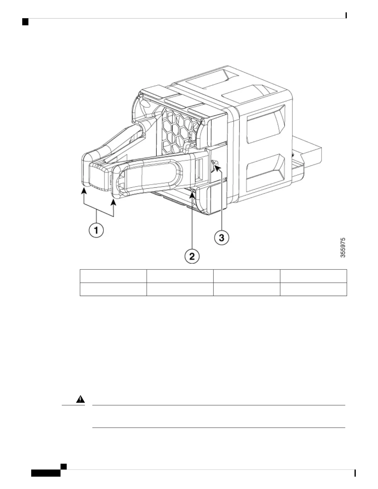
Figure 62: Fan Module
Retainer clip3Extraction handles1
Fan LED2
Installation Guidelines
Observe these guidelines when removing or installing a fan module:
Do not force the fan module into the slot. This can damage the pins on the switch if they are not aligned
with the module.
A fan module that is only partially connected to the switch can disrupt the system operation.
The switch supports hot swapping of the fan module. You can remove and replace the module without
interrupting normal switch operation.
Only trained and qualified personnel should be allowed to install, replace, or service this equipment.
Statement 1030
Warning
Cisco Catalyst 9200 Series Switches Hardware Installation Guide
96
Installing a Fan Module
Installation Guidelines

Table of Contents

Other manuals for Cisco Catalyst 9200 Series

Questions and Answers:

Question and Answer IconNeed help?

Do you have a question about the Cisco Catalyst 9200 Series and is the answer not in the manual?

Cisco Catalyst 9200 Series Specifications

General IconGeneral
CategorySwitch
Stacking Bandwidth160 Gbps
LayerLayer 2 and Layer 3
Operating SystemCisco IOS XE
Operating Temperature0°C to 45°C (32°F to 113°F)
SeriesCisco Catalyst 9200 Series
Ports24 or 48 Ethernet ports
Switching CapacityUp to 176 Gbps
PoEPoE, PoE+, and UPOE
StackingStackWise-160
Memory4 GB DRAM, 4 GB Flash
Network ManagementCisco DNA Center, WebUI, CLI
Security Features802.1X, TrustSec, MACsec
WarrantyLimited Lifetime Warranty
Dimensions1.73 x 17.5 x 11.3 in. (4.4 x 44.5 x 28.8 cm)

Related product manuals