• Management 1/1—Connect Management 1/1 to your management network, and make sure your
management computer is on—or has access to—the management network. Management 1/1 obtains an
IP address from a DHCP server on your management network; if you use this interface, you must determine
the IP address assigned to the ASA so that you can connect to the IP address from your management
computer.
• Ethernet 1/2—Connect your management computer directly to Ethernet 1/2 for initial configuration. Or
connect Ethernet 1/2 to your inside network; make sure your management computer is on the inside
network, because only clients on that network can access the ASA. Ethernet 1/2 has a default IP address
(192.168.1.1) and also runs a DHCP server to provide IP addresses to clients (including the management
computer), so make sure these settings do not conflict with any existing inside network settings (see
Firepower 1100 Default Configuration, on page 158).
If you need to change the Ethernet 1/2 IP address from the default, you must also cable your management
computer to the console port. See (Optional) Change the IP Address, on page 161.
You can later configure ASA management access from other interfaces; see the ASA general operations
configuration guide.
Step 2 Connect the outside network to the Ethernet1/1 interface.
For Smart Software Licensing, the ASA needs internet access so that it can access the License Authority.
Step 3 Connect other networks to the remaining interfaces.
Power on the Device
System power is controlled by a rocker power switch located on the rear of the device. The power switch is
implemented as a soft notification switch that supports graceful shutdown of the system to reduce the risk of
system software and data corruption.
Procedure
Step 1 Attach the power cord to the device, and connect it to an electrical outlet.
Step 2 Turn the power on using the standard rocker-type power on/off switch located on the rear of the chassis,
adjacent to the power cord.
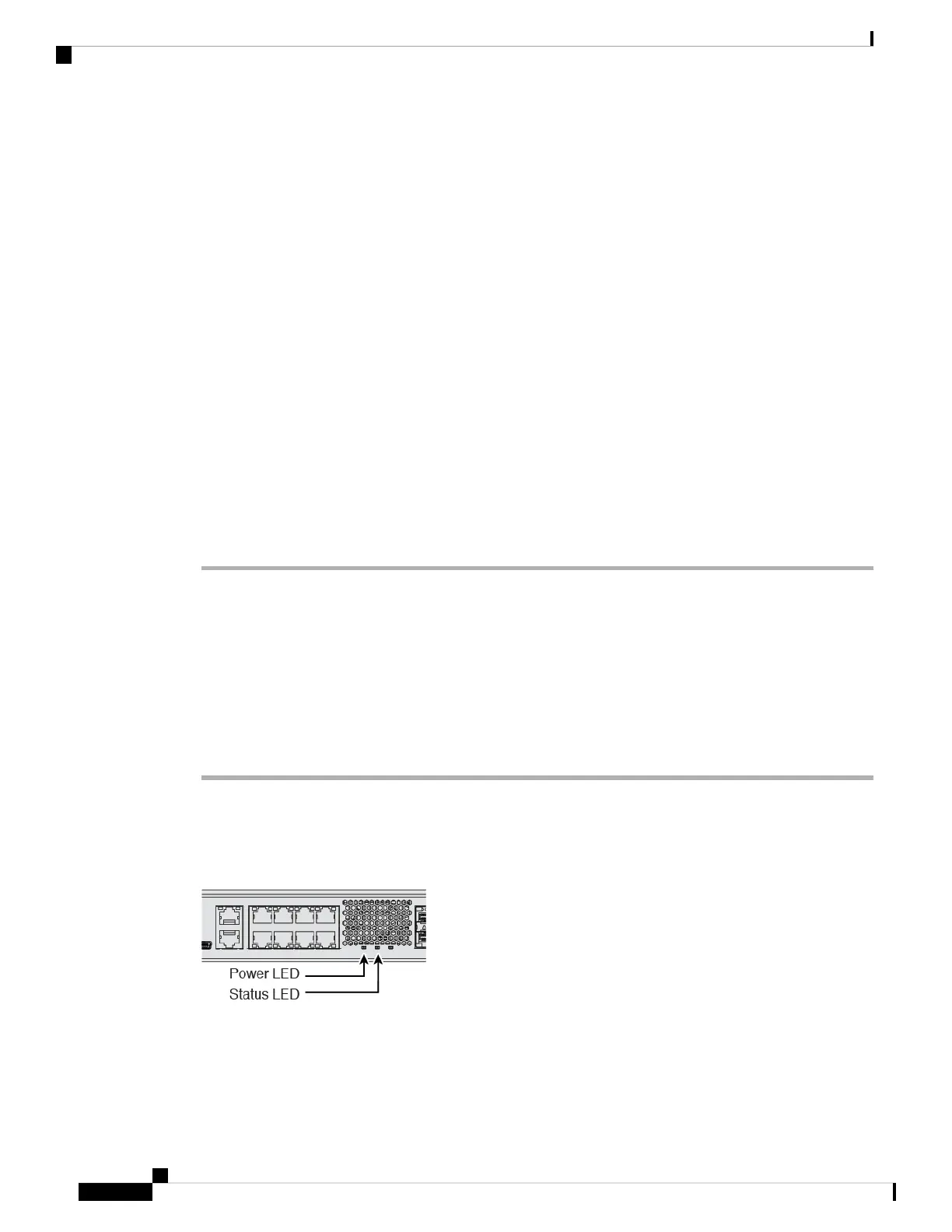
Step 3 Check the Power LED on the back of the device; if it is solid green, the device is powered on.
Step 4 Check the Status LED on the back of the device; after it is solid green, the system has passed power-on
diagnostics.
Cisco Firepower 1100 Getting Started Guide
160
ASA Deployment with ASDM
Power on the Device