4-9
Catalyst 4500 E-Series Switches Installation Guide
OL-13972-02
Chapter 4 Removal and Replacement Procedures
Removing and Installing the DC-Input Power Supplies
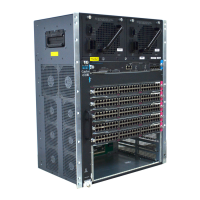
Figure 4-9 DC-Input Power Supply
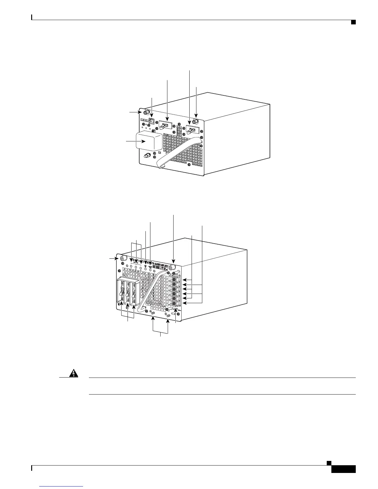
Figure 4-10 DC Triple-Input Power Supply
Step 4 Disconnect the DC-input wires from the terminal block. Disconnect the ground wire last (see
Figure 4-11 or Figure 4-12).
Warning
When installing or replacing the unit, the ground connection must always be made first and
disconnected last.
Statement 1046
Captive screw
Captive screw
In-line power switch
Serial communication
connector
Main power switch
Terminal block
79160
231891
Power switch 1, 2, 3
Terminal block
Ground lugs
Input OK 1, 2, 3 LEDs
Fan OK LED
Output Fail LED
1
-
+
-
+
-
+
2
3
Captive screw
Captive
screw
Minus (-)
Plus (+)
 Loading...


