4-10
Catalyst 4500 E-Series Switches Installation Guide
OL-13972-02
Chapter 4 Removal and Replacement Procedures
Removing and Installing the DC-Input Power Supplies
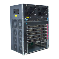
Figure 4-11 Connecting the DC-Input Wires
Figure 4-12 Connecting the DC-Input Wires (Triple-Input Power Supply)
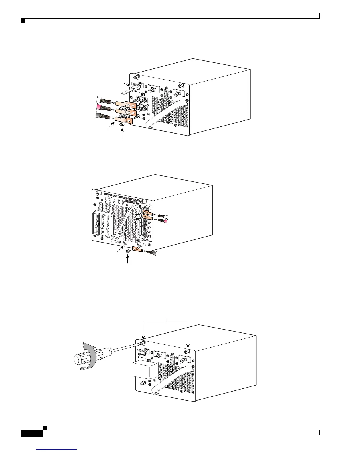
Step 5 Loosen the two captive screws on the power supply. (See Figure 4-13, which shows the single-input
power supply. The triple-input power supply has captive screws in the same location.)
Figure 4-13 Loosening the Captive Screws
RS-485 serial
communnication
connector
79161
Grounding lug
Grounding lug nuts
DC-input wires
Negative
Positive
Ground
231892
1
-
+
-
+
-
+
2
3
Grounding lugs (2)
Grounding lug nut
DC-input wires
Negative
Positive
Ground
Captive screws
79162
 Loading...


