n+n redundancy mode
Half of the 3-kW power supplies are connected to one power source (grid) and the other half are
connected to another power source. The available power is provided by one power source and the
reserve power is provided by the other power source. If the power source that provides the available
power fails, the switch uses the reserve power source to provide its required power. You activate this
power mode by using the power redundancy-mode insrc_redundant command.
For example, if the power requirement for a switch is 5.2 kW and the switch has two power supplies
that output 3 kW, consider the following power planning scenarios:
• Scenario 1—No added power supplies
The available power is 3.0 kW (output from one 3-kW power supply) and the reserve power is
3.0 kW (output from the other power supply). The available power (3.0 kW) does not meet the
switch requirements (5.2 kW), so most of the modules will power up but some of the line cards
will not be able to power up.
• Scenario 2—Adding two 3-kW power supplies
The available power is 6.0 kW (output from two 3-kW power supplies on grid A) and the reserve
power is 6.0 kW (output from the other two power supplies on grid B). The available power (6.0
kW) exceeds the power requirement of the switch (5.2 kW), so the entire switch can power up.
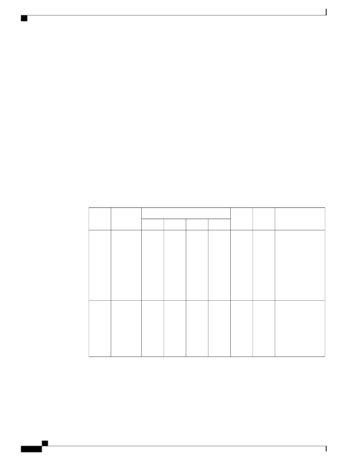
The following table shows the results for each scenario.
ResultReserve
Power
Available
Power
Output for Power SuppliesPower
Requirement
Scenario
4321
Available power
(3.0 kW) is less than
the power
requirement for the
switch (5.2
kW)—switch
powers up but some
of the line cards
cannot power up.
3.0 kW3.0 kW
——
3.0 kW3.0 kW5.2 kW1
Available power
(6.0 kW) exceeds
the power
requirement for the
switch (5.2
kW)—entire switch
powers up.
6.0 kW6.0 kW3.0 kW3.0 kW3.0 kW3.0 kW5.2 kW2
For grid redundancy mode, the power supplies must be divided into two equal sets and installed as
follows:
•
Slots labeled as PS 1 to PS 4 must be connected to one grid (Grid A)
•
Slots labeled as PS 5 to PS 8 must be connected to another grid (Grid B)
Cisco Nexus 9508 NX-OS Mode Switch Hardware Installation Guide
72
Managing the Switch
Power Mode Configuration Guidelines
 Loading...