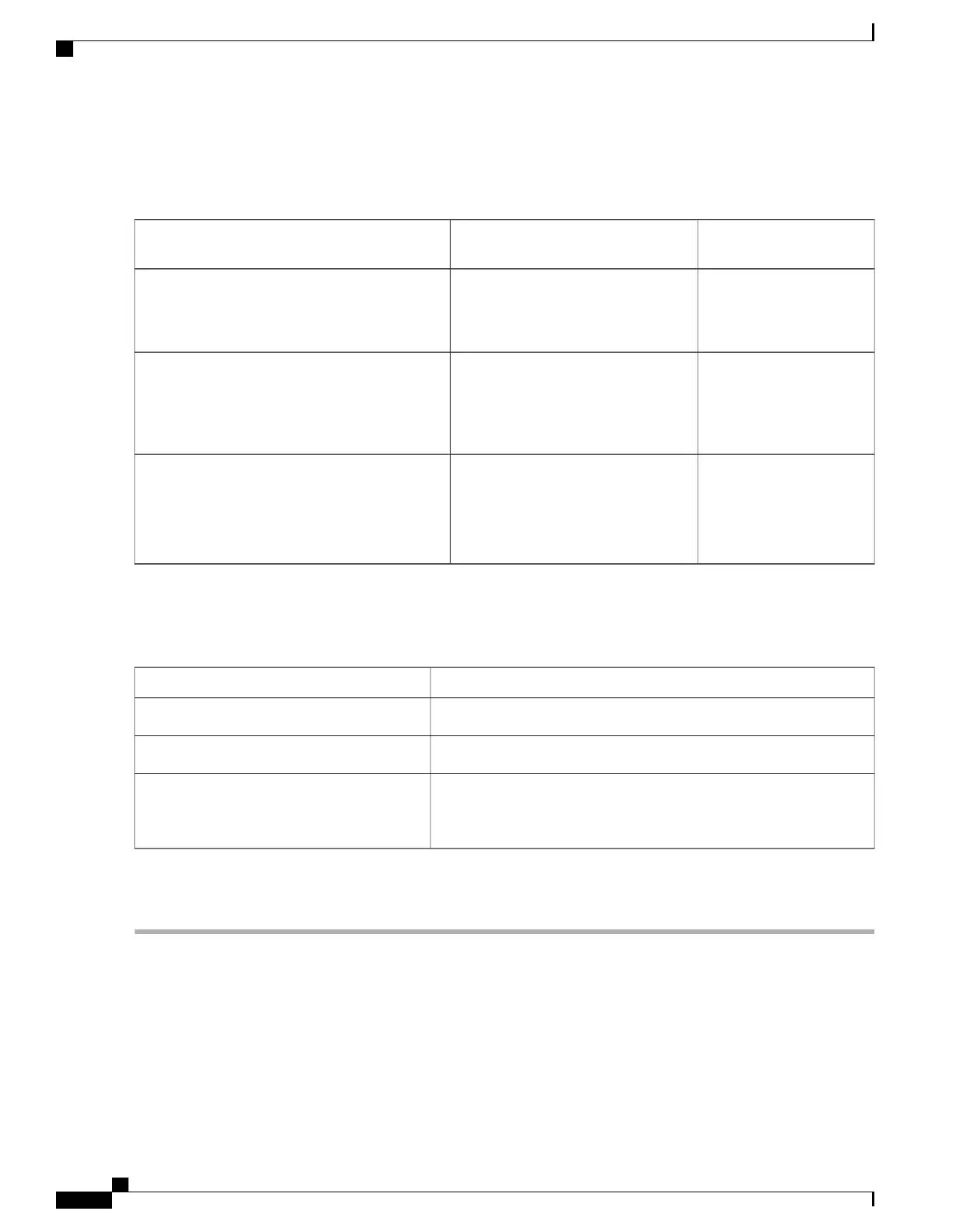
For combined mode or n+1 redundancy mode, you need only one dedicated circuit. For n+n redundancy, you must have
two dedicated power circuits, with each circuit powering half of the 3-kW power supplies. The requirements for each
circuit are listed in the following table.
Requirement for Each
Circuit
Number of CircuitsPower Supply
16 A at 200 to 240 VAC
1 (combined mode or n+1 redundancy
mode)
2 (n+n redundancy mode)
3-kW AC power supply (N9K-PAC-3000W-B)
AC power: 200 to 277
VAC
DC power: 240 to 380
VDC
1 (combined mode or n+1 redundancy
mode)
2 (n+n redundancy mode)
3-kW Universal AC/DC power supply
(N9K-PUV-3000W-B)
45A at -40 to -75 VDC
(-48 VDC nominal US)
(-60 VDC nominal
international)
1 (combined mode or n+1 redundancy
mode)
2 (n+n redundancy mode)
3-kW DC power supply (N9K-PDC-3000W-B)
Step 6
Plan the placement of the input power receptacles within reach of the power cables used for each power supply (see the
following table for the maximum distances).
Typically, power receptacles are placed on the rack with the switch.
Maximum Distance Between Receptacle and Power SupplyPower Supply
8 to 12 feet (2.5 to 3.5 m)3-kW AC power supplies
14 feet (4.27 m)3-kW Universal AC/DC power supplies
Customer provides four 6-gauge wires (recommended) and cuts that
wire to the required length. Cisco provides four 6-gauge lugs to connect
those wires to the DC power supply.
3-kW DC power supplies
All power supplies installed in the same switch must be powered by either AC power sources or DC power
sources, not by a mix of AC and DC power sources.
Note
Rack and Cabinet Requirements
You can install the following types of racks or cabinets for your switch:
•
Standard perforated cabinets
Cisco Nexus 9508 NX-OS Mode Switch Hardware Installation Guide
14
Preparing the Site
Rack and Cabinet Requirements

 Loading...