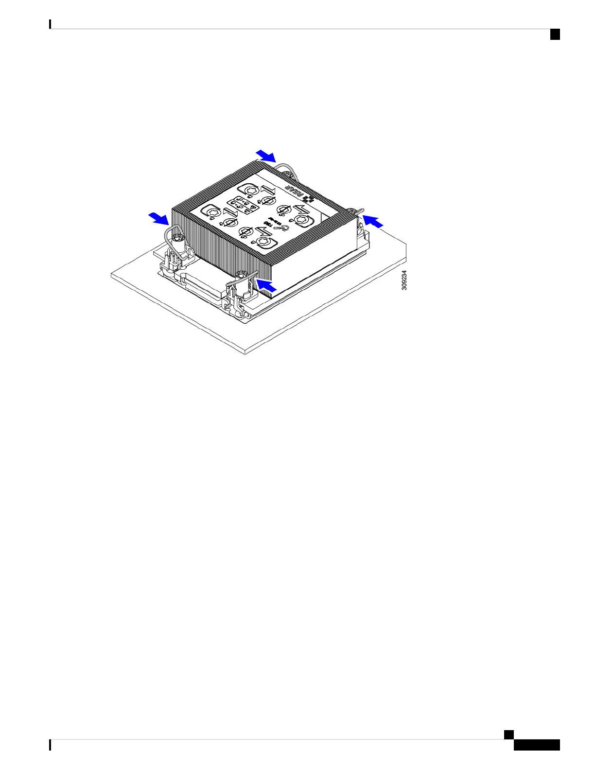
b) Push the rotating wires towards each other to move them to the unlocked position.
Make sure that the rotating wires are as far inward as possible. When fully unlocked, the bottom of the
rotating wire disengages and allows the removal of the CPU assembly. If the rotating wires are not fully
in the unlocked position, you can feel resistance when attempting to remove the CPU assembly.
Caution
Step 2 Remove the CPU assembly from the motherboard.
a) Grasp the heatsink along the edge of the fins and lift the CPU assembly off of the motherboard.
While lifting the CPU assembly, make sure not to bend the heatsink fins. Also, if you feel any resistance
when lifting the CPU assembly, verify that the rotating wires are completely in the unlocked position.
Caution
b) Put the CPU assembly on a rubberized mat or other ESD-safe work surface.
When placing the CPU on the work surface, the heatsink label should be facing up. Do not rotate the CPU assembly
upside down.
c) Ensure that the heatsink sits level on the work surface.
Cisco UCS X210c M6 Compute Node Installation and Service Note
37
Servicing a Compute Node
Removing the CPU and Heatsink
 Loading...