Step 3 Attach a CPU dust cover (UCS-CPU-M6-CVR=) to the CPU socket.
a) Align the posts on the CPU bolstering plate with the cutouts at the corners of the dust cover.
b) Lower the dust cover and simultaneously press down on the edges until it snaps into place over the CPU socket.
Do not press down in the center of the dust cover!
Caution
Cisco UCS X210c M6 Compute Node Installation and Service Note
38
Servicing a Compute Node
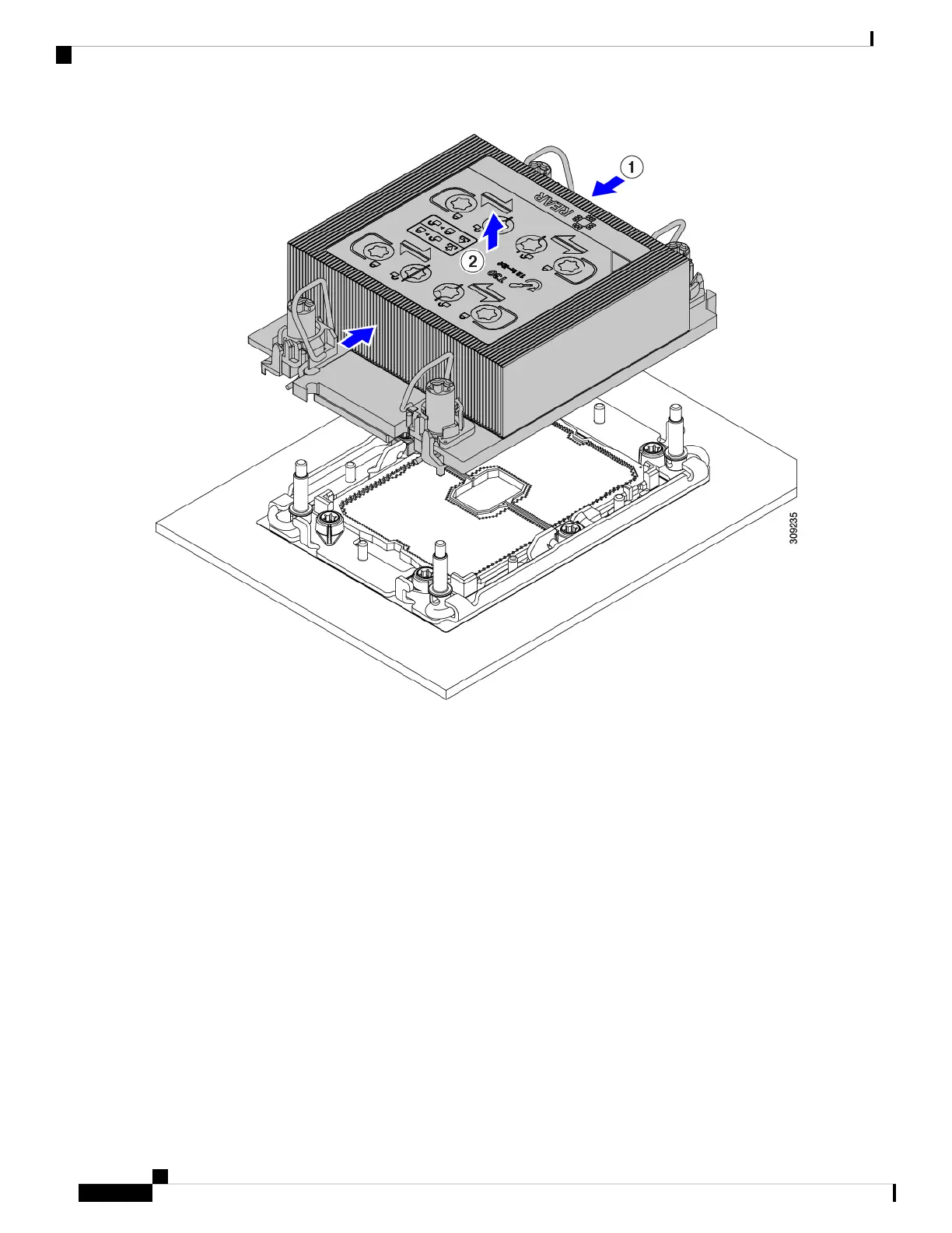
Removing the CPU and Heatsink
 Loading...