• x4 DIMMs are supported.
• DIMMs must be loaded lowest number slot first.
• Memory ranks are 64- or 72-bit chunks of data that each memory channel for a CPU can use. Each
memory channel can support a maximum of 8 memory ranks. For quad-rank DIMMs, a maximum of 2
DIMMs are supported per channel (4 ranks * 2 DIMMs).
• Mixed ranks of DIMMs are allowed in the same channel, but you must populate higher quantity rank
DIMMs in the lower numbered slots.
• All slots must be populated with either a DIMM or a DIMM blank.
• Validation on all permutations for 100% test coverage is not supported. See the DIMMs Population
Order table for supported configurations.
• It’s important to balance population between each CPU and each memory controller in each CPU to
optimize memory capacity, except for single DIMM per CPU configurations, which should be loaded
with the higher capacity DIMM on CPU1.
DIMM Identification
To assist with identification, each DIMM slot displays its memory processor and slot ID on the motherboard.
For example, P1 A1 indicates slot A1 for processor 1.
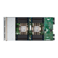
Also, you can further identify which DIMM slot connects to which CPU by dividing the blade in half vertically.
• All DIMM slots on the left are connected to CPU 1.
• All DIMM slots on the right are connected to CPU 2.
For each CPU, each set of 16 DIMMs is arranged into 8 channels, where each channel has two DIMMs. Each
DIMM slot is numbered 1 or 2, and each DIMM slot 1 is blue and each DIMM slot 2 is black. Each channel
is identified by two pairs of letters and numbers where the first pair indicates the processor, and the second
pair indicates the memory channel and slot in the channel.
• Channels for CPU 1 are P1 A1 and A2, P1 B1 and B2, P1 C1 and C2, P1 D1 and D2, P1 E1 and E2, P1
F1 and F2, P1 G1 and G2, P1 H1 and H2.
• Channels for CPU 2 are P2 A1 and A2, P2 B1 and B2, P2 C1 and C2, P2 D1 and D2, P2 E1 and E2, P2
F1 and F2, P2 G1 and G2, P2 H1 and H2.
The following illustration shows the memory slot and channel IDs.
Cisco UCS X210c M6 Compute Node Installation and Service Note
48
Servicing a Compute Node
Memory Population Guidelines

 Loading...