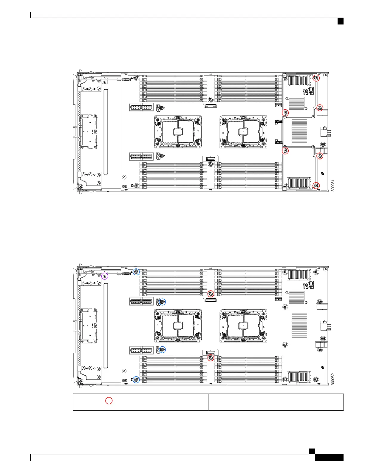
c) Turn the compute node component side up and use the T10 screwdriver to remove the six M3 mounting screws at
the rear of the compute node.
Step 8 If the TPM is installed, remove it.
See Removing the Trusted Platform Module (TPM), on page 61.
Step 9 Disconnect the motherboard from the compute node's sheet metal.
a) Use the 6mm hex nut driver to remove the two standoffs.
b) Use the #2 Phillips screwdriver to remove the front mezzanine cage retaining screw, then remove the cage.
c) Use the T10 screwdriver to remove the four M3 screws.
6 mm standoffs (2)
Red circles ( )
Cisco UCS X210c M6 Compute Node Installation and Service Note
73
Servicing a Compute Node
Recycling the PCB Assembly (PCBA)
 Loading...