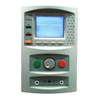
Lea
– this is the upper limit for the leakage current.
L
– this is the lower limit for the leakage current. It is used to
determine that a EUT is correctly connected.
– this shows the level set for the detection of any arc that
may occur in the EUT, during testing.
– shows the action needed to initiate the test sequence. This
refers to the usage of the e
ernal safety guard switch
only
, the
ernal guard switch
and
the G
button or the G
button
only
.
T
est status – here this shows that the test is in the hold phase. This
part of the display is used to indicate what part of the test cycle is
being performed.
Elapsed t
– this is shown below the test status.
H
V
– this is displayed to show that a voltage is being generated by
the tester, and if connected, will appear at the EUT.
⊕
1 ⊕ (Hal 102) This icon indicates which active terminal output
channel pair is selected.
F
R
Ground Bond or
Earth Bond Test
Leak Hi
Leak Lo
Arc detect
Start
ext
ext Green Green
Test status
test time
HV icon
1
F
R
Ground Bond or
Earth Bond Test
Leak Hi
Leak Lo
Arc detect
Start
ext
ext Green Green
Test status
test time
HV icon
1
F
R
Note: if both the F & R icons are enabled, the tester will perform the
test twice, once for the front output and then the rear output with a
prompting in between the tests.
Ground Bond or
Earth Bond Test
Leak Hi
Leak Lo
Arc detect
Start
ext
ext Green Green
Test status
test time
HV icon
1
F
R
Ground Bond or
Earth Bond Test
The
right panel
of the display shows the output voltage and leakage
current or insulation resistance, depending on which test is being
applied.
 Loading...