22 Tempest®2400 2-Channel Wireless Intercom System
Boom view of the transceiver
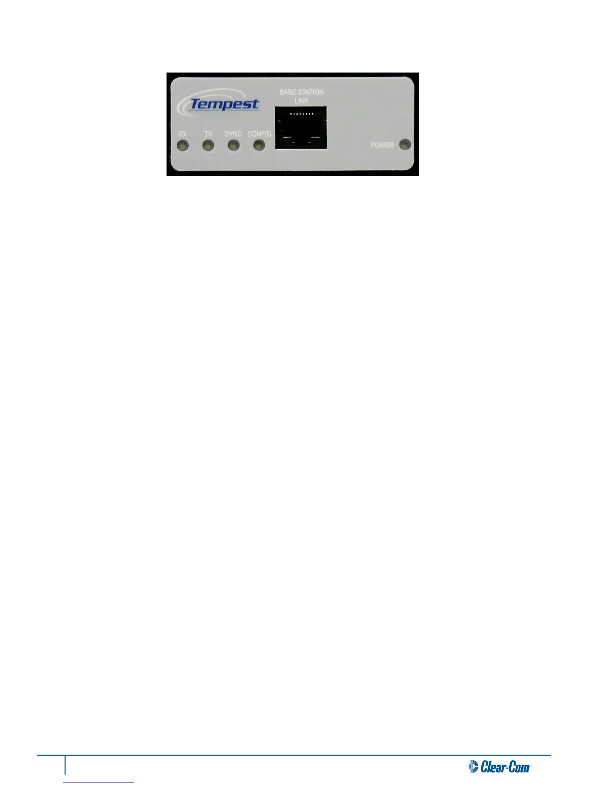
Transceiver Controls
1- RX LED
The RX LED illuminates when data is being received by the Remote Transceiver. This LED will remain illuminated during
normal system operaon.
2- TX LED
The TX LED illuminates when data is being sent from the Remote Transceiver. This LED will remain illuminated during
normal system operaon.
3- SYNC LED
The Sync LED illuminates when the Transceiver Sync signal is present. This LED will remain illuminated during normal
system operaon.
4- CONFIG LED
The Cong LED illuminates only when the BaseStaon puts the Remote Transceiver into conguraon mode to change
sengs. This LED should be ON for only a few seconds when rst powered ON, and OFF during normal operaon.
5- BASESTATION LINK RJ-45 Connector
The BaseStaon Link RJ-45 connector is used to connect the Transceiver to the Tempest BaseStaon via standard CAT-5
cable with RJ-45 connectors.
6- Power LED
The Power LED illuminates whenever the BaseStaon is providing adequate power to the Transceiver over the CAT-5 cable.
If the Power LED does not light, the CAT-5 cable may be damaged or too long to deliver adequate power for the Transceiver
to operate reliably.
Threaded Mounng Holes
Two Threaded Mounng Holes are provided on the back of the Remote Transceiver for use with the mounng bracket to
mount the Transceiver in a convenient locaon. The mounng holes are #8-32 thread and accept a #8-32 x 3/8” pan head
screw.

 Loading...