750-382
CBT
2-5
Gas Piping
2.4 — Gas Piping
Gas pressure requirements - For proper and safe operation, each Model CBT boiler requires a stable gas pressure
input. The minimum inlet supply pressure must be as noted in Table 2-3. Pressure should be measured when the
burner is firing using a manometer at the upstream test port connection on the main gas valve. For a multiple
unit installation, gas pressure should be set for a single unit first, then the remaining units should be staged on to
ensure that gas pressure droop is not more than 1" w.c. and never below the required pressure. Fluctuating gas
pressure readings could be indicative of a faulty supply regulator or improper gas train size to the boiler.
*Maximum without upstream regulator
A manually operated shut-off valve is provided as standard on the CBT boiler. If dirt particles are present in the
gas supply, it may be necessary to install an approved gas filter. Please inquire with the local gas supply company.
The boiler shall be installed such that the gas ignition system components are protected from water (dripping,
spraying, etc.) during appliance operation and service.
TABLE 2- 3. Model CBT gas pressure requirements
CBT Size
(HP)
Natural Gas LP Gas
Min (“WC) Max (“WC)* Min (“WC) Max (“WC)*
10 7.0 14 11.0 14
15 7.0 14 11.0 14
20 7.0 14 11.0 14
25 7.0 14 11.0 14
30 8.0 14 11.0 14
A sediment trap must be provided upstream of the gas controls.
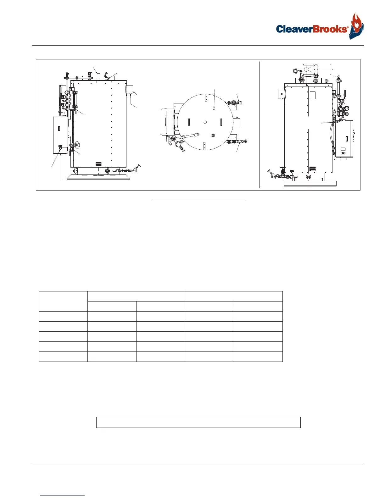
FIGURE 2-3. CBT connections
STACK OUTLET
CONDENSATE
DRAIN
SAFETY RELIEF VALVE
WATER COLUMN
DRAIN
GAS
INLET
GAS INLET
ON/OFF UNITS
STEAM OUTLET
COMBUSTION AIR INLET
SURFACE BLOWOFF
FEEDWATER
BOTTOM
BLOWDOWN
GAUGE
GLASS
DRAIN