750-382
CBT
3-9
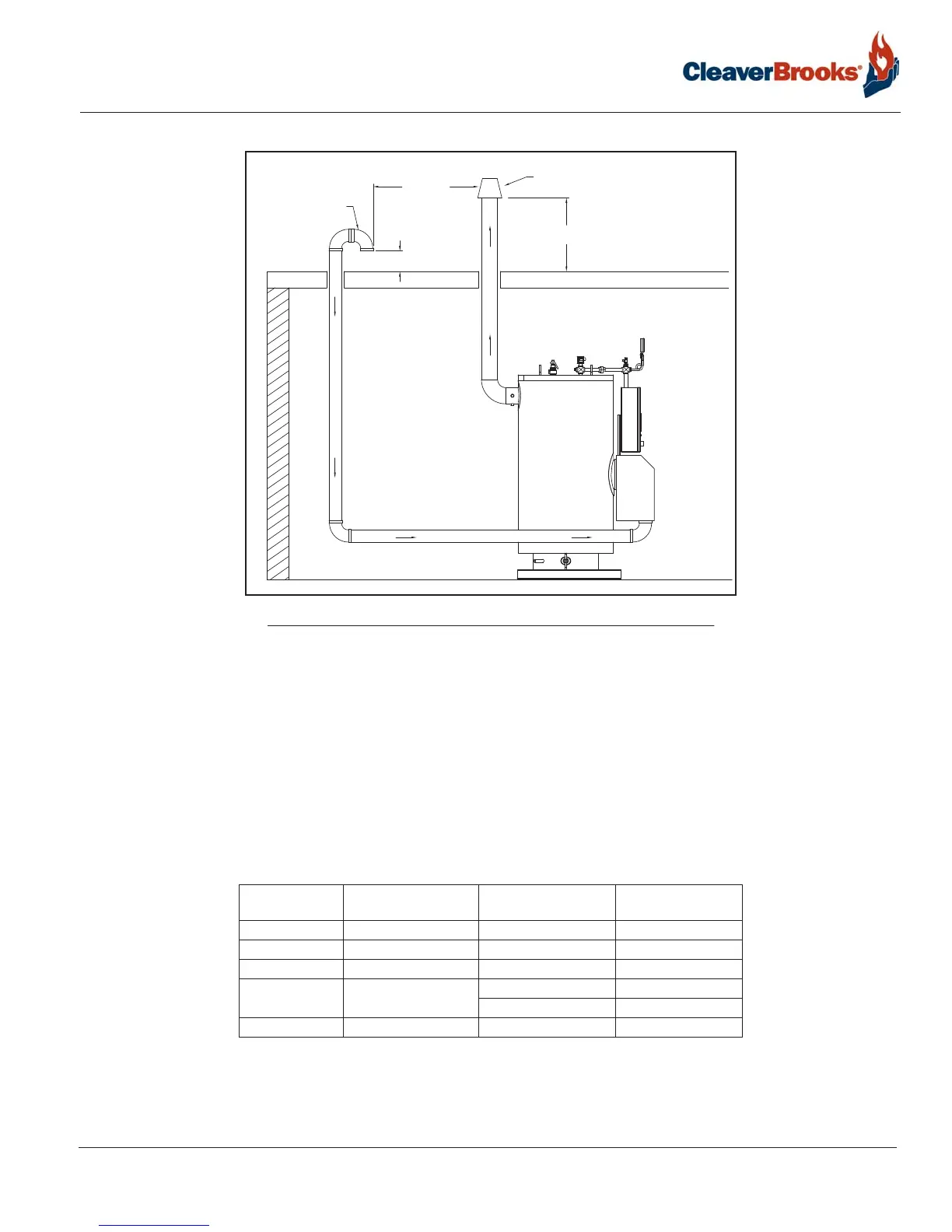
Vertical venting direct vent combustion air (Category III)
3.8 — Vertical venting direct vent combustion air (Category III)
These installations utilize the boiler mounted blower to draw combustion air from outside and vent combustion
products to the outside. A positive pressure venting system is required.
To prevent condensation accumulation in extended horizontal runs, it is required to install the horizontal portion
of the flue venting with a slight upward slope of at least 1/8” per foot of horizontal run; a drain with condensate
trap must be installed per applicable codes.
Combustion air venting can be constructed of steel, stainless steel, PVC, CPVC, or material as deemed appropri-
ate for the application and per local codes.
3.9 — Flue and combustion air duct design using direct vent combustion air
*Each additional 90 deg. elbow equals 5 equivalent feet of ductwork. Subtract from the maximum length accordingly. Increasing
the diameter of the air intake will reduce the pressure drop and thereby allow longer total vent lengths. Maximum allowable pressure
drop in combustion air intake duct is 0.25” w.c.
**The maximum allowable draft tolerance in the flue venting is +/- 0.25” w.c. as measured at the boiler's flue outlet.
Boiler Size HP Stack Connection - Flue
diameter (in)**
Combustion Air Duct
diameter (in)
Maximum Air Intake
Length (ft)*
10 6 4 160
15 6 4 140
20 6 4 120
25 6
4 100
6 140
30 8 6 120
Air Intake
(w/Screen)
36”
Minimum
12” Minimum
24” Minimum
Flue Vent Termination
(velocity cone type)
FIGURE 3-5. Vertical stack with direct vent combustion air