Commissioning
4-18
750-382
CBT
8. The ignitor is turned off at the end of the direct burner ignition period.
9. The fan is kept at the lightoff rate during the stabilization time.
10.Release to modulation.
11.At the end of the heat request the burner is switched off and the fan stays on until post purge is complete.
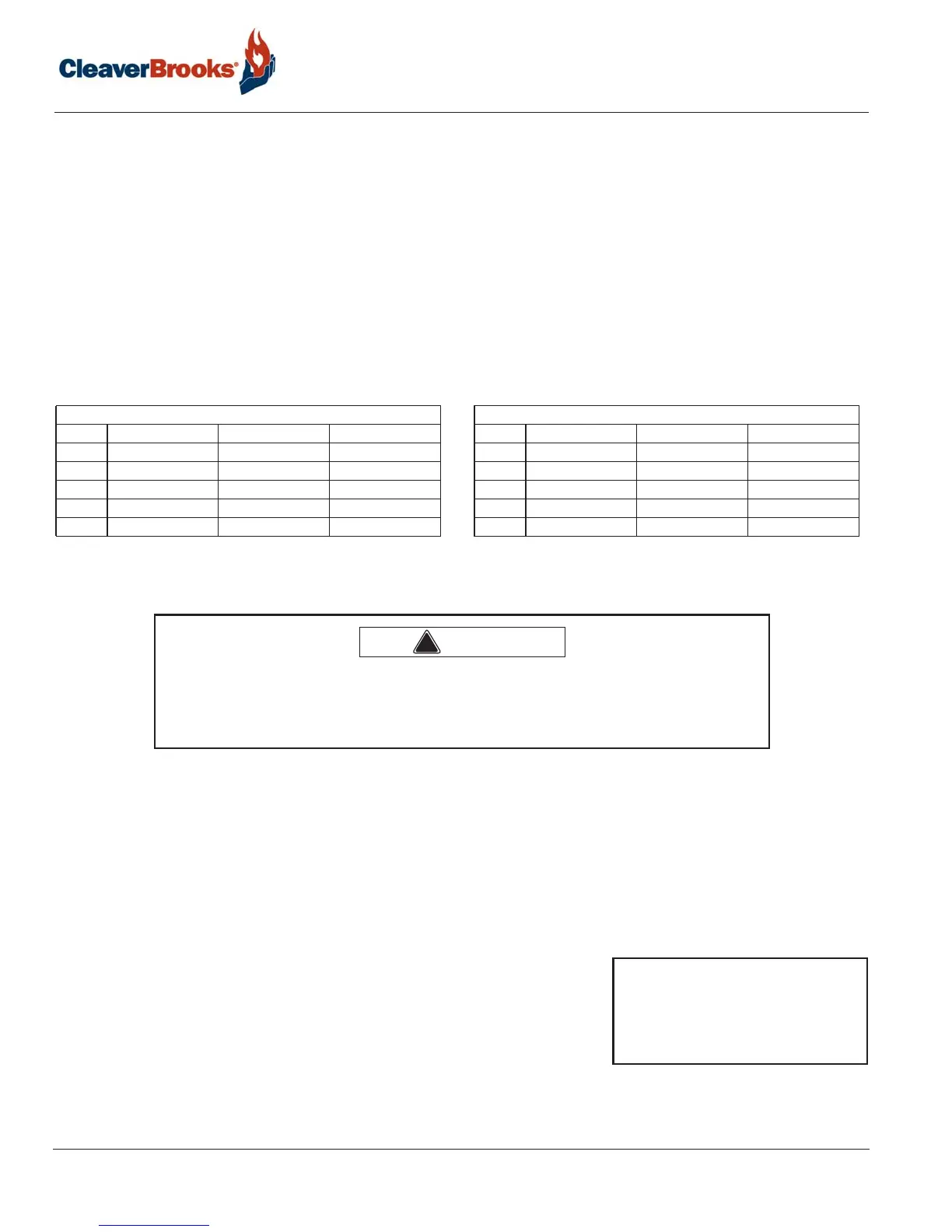
4.1.11 — Fan speed settings
The boiler firing rate is determined by the combustion air fan speed. Accordingly, fan speed settings may have
to be modified for the particular application, for high altitudes, or when using direct vent combustion. The table
below provides the default fan speed settings in typical applications for the various boiler sizes. To allow safe
modulation through the firing range, these parameters should be initially set to the recommended speeds.
Please contact your authorized Cleaver-Brooks representative for proper settings in high altitude and direct vent
combustion applications.
TABLE 4- 2. Fan Speed Settings RPM
4.1.12 — Initial startup procedure
4.1.13 — Gas train and piping
The burner is equipped with a combination servo-regulated gas valve and venturi mixing unit. The gas valve
consists of a single body with dual solenoid shut off valves, filter screen, and a built-in constant pressure gas/
air servo controller. The blower speed is controlled by the CB Falcon with airflow directly proportional to the
speed of the fan. The airflow creates a drop in pressure due to the venturi effect. The modulating controller of
the valve actuator senses air pressure change and brings about a change in the gas flow proportional to the air
flow. The gas follows the airflow in a set ratio, so that fuel always matches the air as the burner firing rate
increases or decreases.
1. Check the gas delivery system to be sure it is properly piped and wired.
2. Review available gas pressure to assure it is compatible with the main
gas regulators upstream of the Model CBT gas train. Note: The
maximum rated inlet pressure to the CBT gas train is 1 psig (28" WC).
An upstream regulator and overpressure protection are required if
building supply gas pressure is greater than 1 psig.
3. To bleed air from the supply pipe, open the manual gas shut off valve upstream of the burner gas train and
bleed air from the piping by loosening the union in the upstream piping or opening the inlet gas test cock.
Natural Gas Propane
HP Max - High Fire Min - Low Fire Ignition HP Max - High Fire Min - Low Fire Ignition
10 5600 1300 2200 10 5200 1100 2200
15 5300 1300 2200 15 4900 1200 2200
20 5300 1300 2000 20 4600 1100 2000
25 5400 1200 2000 25 5000 1300 2000
30 6000 1100 1800 30 5700 1200 1800
!
Warning
Before initial startup, check for blockages in the flue venting or vent
terminations. Inspect the burner and furnace for any contamination
or blockages.
Note: To measure supply pressure
at the CBT gas valve, use the
test port on the valve inlet
flange. Do not use the leak
test cocks to measure gas
pressure.