Installation
2-8
750-382
CBT
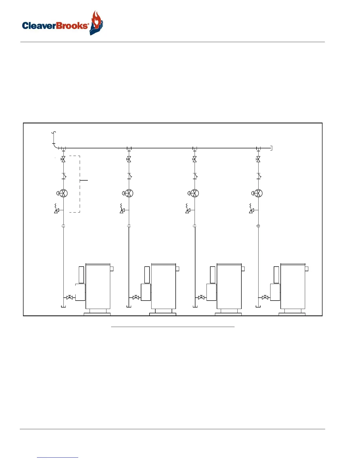
Gas header - For multiple unit installations, a single common gas header is recommended with individual
takeoffs for each boiler (See Figure 2-4). Boiler gas manifold piping should be sized based on volume
requirements and lengths between each boiler and the fuel main header. Tables 2-6 through 2-10 indicate the
proper sizing for multiple units of equal size, placed on the factory standard center with the indicated take off
size. For installations with a mixed sized use, determine the flow of each unit and total the input. With the total
input, find length of run from the source and determine what size header will be needed for the flow of all units
firing. Pipe sizes are based on Table 2-4 with boiler gas line take-off at 20 feet from the header. If pipe runs are
greater or if gas pressure is different, refer to Tables 2-4 and 2-5 for pipe sizing. Main fuel supply header should
be sized for <4" w.c. pressure drop with all equipment operating at 100% capacity.
FIGURE 2-4. Typical gas piping - Example 1
MANUAL
SHUTOFF
DRIP LEG
MANUAL SHUTOFF
GAS STRAINER
REGULATOR
SEE NOTE 1
RELIEF VALVE
SEE NOTE 5
OPTIONAL
FROM METER
HEADER PIPE
NOTES:
1. Step-down regulator required
if supply pressure >1/2 psig.
2. Refer to local fuel gas codes when
applicable.
3. Header to be sized for room
capacity.
4. Provision required for measuring
gas supply pressure at boiler.
5. Relief valve required if gas supply
pressure >1 psig.